|
WAR GAMING - PAN & TILT SAM TURRETS to 1/20th scale
|
|||||||||||||||||||||||||||||||||||||||||||||||||||||||||||||||||||||||||||||||||||||||||||||||||||||||||||||||||||||||||
|
We are using these value packs to begin our experiments. Even at 1/10th scale, war-gaming should be economical. Buying the donor rocket motors this way works out at £1 a shot. If a club were to make a bulk purchase, this could be reduced to £0.50p a shot. Compare that to the £millions that the military spend - and it's a cheap way of developing weapon systems. The downside is that they are quite a bit larger than the scale size of a Rapier SAM - meaning that we are going to have to compromise.
We need to make 4 SAM batteries for our /20th scale HK model. These turrets are to have the same functions as the full size drone ship. This means rotation and swivel elevation, up and down, commonly known as pan and tilt. Each turret will have a sensor array to at least include a mini camera and infra red motion detectors. Laser ranging would be better. Maybe, if we can source the components at sensible prices.
The missiles are to be based on ordinary bonfire night type sky rockets, hence will require considerable modification - and you should not try this at home unless you are an experienced modeler, or work under the supervision of an experienced adult modeler or teacher. Our team of model engineers are highly skilled veterans.
A SAM is basically just a solid propellant rocket with a guidance system and an explosive warhead. We don't need an explosive warhead for gaming purposes, but some clubs do like a good display and try to sink each others boats. Game on.
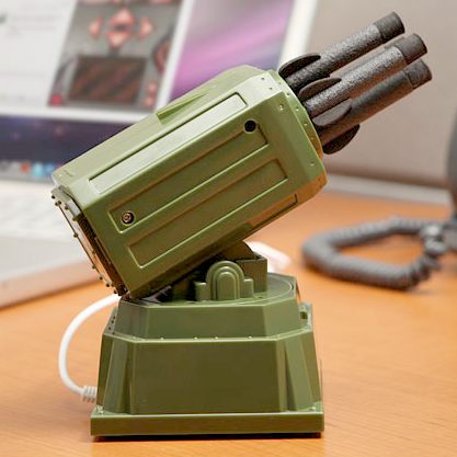
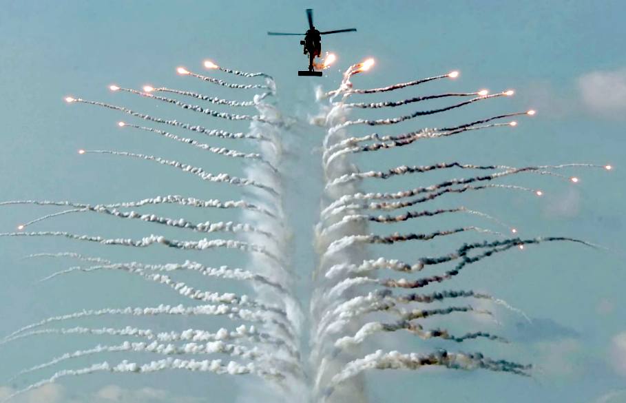
In this case the SAMs are to take down drone aircraft. Now that could be fun war-gaming, using quadcopter drones as targets. One quadcopter in particular has a camera onboard and fires plastic projectiles from a Gatling gun. It can also be fitted with a water cannon. But can it make the tea? See the FBQC article below.
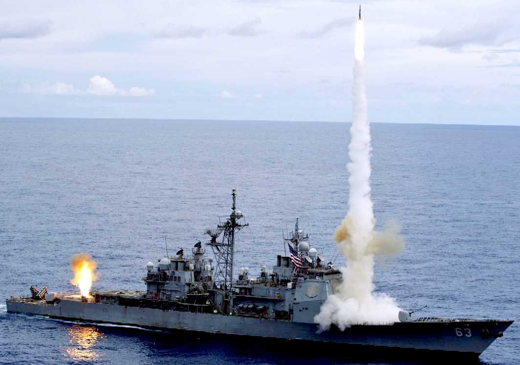
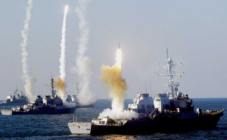
This is what it is all about. Getting your missiles launched before the other side get one off at you. These warships are woefully under-gunned compared to a Scorpion HK. They'd be sushi in a matter of seconds with a cruise missile strike. Mind you, a couple of meaty SAMs might do the trick on these small ships.
MOVEMENT = R/C SERVOS
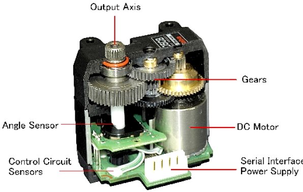
To power our pan and tilt turrets we need 8 servos. Servos are small DC motors that come in a convenient package with a gearbox. They incorporate a feedback loop - the output shaft of the servo is connected to a potentiometer which measures its current position. This allows the shaft to be set to specific angles by sending the servo a coded signal. The downside is that the shaft can't rotate through the full 360 degrees, making them useless as drive motors. It is possible to modify servos to rotate continuously.
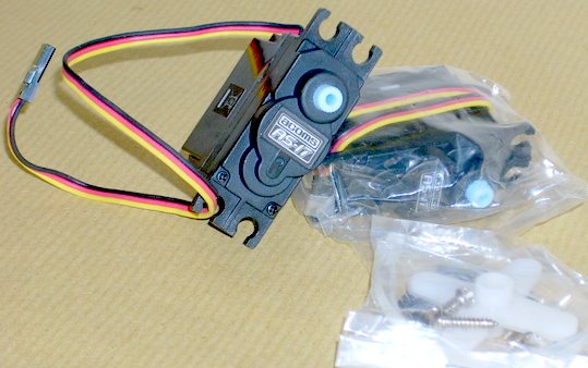
LEFT - The Acoms AS17 is a reliable servo at an affordable price. RIGHT - This is a Futaba RS 405CB servo with metal gears. Metal gears wear quicker, but can handle a lot more torque. The ultimate is titanium gears - but the cost is prohibitive, except for scientific or military production.
ACOMS
AS17 High Speed Servo
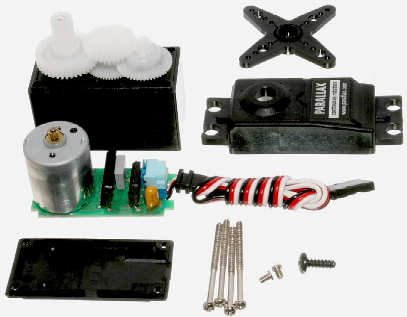
LEFT
- Giant sail winch servo. CENTRE - parts of a standard nylon geared servo.
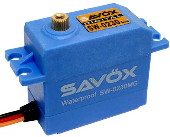
RIGHT - The Savox SW0230MG is a budget friendly waterproof digital servo capable of operating at 6.0V and 7.4V. This brushed servo features a quick speed of .13 and 111.1 oz-in of torque @ 7.4V. It combines leading edge technology with super high 12-bit (4096) resolution and strong metal gears for your greater precision. This is a great upgrade if your looking to drive your RC vehicle in any condition at sea: rain, sleet, or snow.
Spec check: Dims: 41.8x20.2x38.0mm, Weight: 59 grams, Speed @6.0V sec/60: .16,
Torque @6.0V oz-in: 90.3, Speed @7.4V sec/60: .13 Torque @7.4V oz-in: 111.1 (8kg),
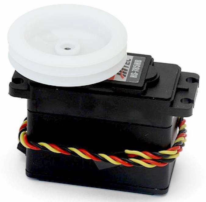
The HS-785HB sail winch servo has up to 3.5 turns of travel and comes with a heavy duty drum. With its top ball bearing supported output shaft the HS-785HD should provide years of reliable service.
Motor Type : 3 Pole Ferrite
This is the servo that we are considering using to rotate (pan) the SAM turret. It is a lot taller and longer than the Acoms AS17, but with dual ball bearing supporting the whole assembly it is sure to offer a steadier movement. Hence, more accuracy in tracking and launching the SAMs.
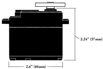
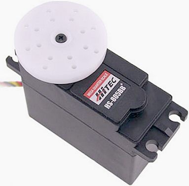
HITEC MONSTER SERVO
Way over the top for our application, but we like it. The HS-805BB uses a heavy duty nylon gear train and a heavy duty 10mm 15 tooth output shaft. If you are needing power, look no further than the HS-805BB servo. At 6 volts, this servo unleashes an amazing 343 oz-in. of torque. Dual ball bearings, extra thick nylon gears, heavy H-bridge and large output spline enable the HS-805BB to handle almost anything. We offer this servo in several configurations, reverse rotation, 180° rotation and continuous rotation for wheeled applications.
Control System: +Pulse Width Control 1500usec Neutral
HK DIAGRAM 1 - This is a view of a Scorpion HK cruising toward you with Rapier sized missiles aimed head on. Two turrets are visible, starboard and port. An expanded view of one of the turrets is seen below. Please note that although 8 SAMs are shown in the diagrams, we are making the 1/20th turrets with just 4 missiles - as per the revised diagram that shows standard Acoms AS17 servos to scale for the tilt mechanism, but leaving a space for the Hitec Jumbo servo for panning - where a heavy duty ball bearing mounted head will be steadier. Note that with this diagram, the Rapier missile turrets are below the ships deck.
Where a Rapier SAM missile is 2.235m long (hence 112mm @ 1/20th scale) our working models will be 200mm long and between 23-26mm in diameter, with fins having a 45mm wingspan. Bear in mind that Rapiers are a small SAM. The Russian S-75 Dvina missile is over 10m long and the Nike Ajax is 9.96m with a 1.3m wingspan. The weight of each missile will be between 35-40 grams. multiplied by 4, and that gives us 200 grams of payload mass for the AS17 servos to cope with, plus whatever the pan and tilt mechanism adds to the party, and of course, whatever the servos will weigh. It looks like we should be allowing 400 grams as the all up weight. No problems with that!
HK DIAGRAM 2 - HK Diagram 1. showing Rapier SAMs can be ignored for the 1/20th development model, which now looks like this (directly above). The drawing above shows a revised turret design with clearance to house the Acoms AS17 servos and swing the larger rockets towards the sky and rotate them 360 degrees without fouling. Note also that the whole assembly has been raised level with the deck to give clearance to the larger missiles for vertical firing. See the individual drawings through HK3 to HK7 below for more detail.
HK DIAGRAM 3 - This is a view of the model's SAM turret facing forward (at you) you can see that the Acoms AS17 servos are side on (tilt) and end on (pan) in a pan and tilt combination. The Acom AS17 (shown) should be replaced with a Hitec jumbo - there is space for this. The servos and missiles are drawn to scale. But, making and measuring the brackets should only be done with the (actual) servos that are being used - to hand - such as to be able to check dimensions and fit. The servos are shown shaded in a lighter gray and the pan & tilt brackets in a darker gray. One side of the servo is the driving head. The other side is a dummy bearing that might be bonded or screwed to the servo casing. The driving head is usually screwed or bolted to a bracket. Note that the frontal area is reduced head into the wind, though the clearance for rotation of the turret is the same as with the side view of the base fairing, which is longer to accommodate the pan servo.
The saddles that hold the missiles in place, should also allow release on firing, no matter if inverted. The design for this is flexible at the moment, as is the firing mechanism. To fire a skyrocket you simply have to light the fuse. Thus, we are looking at various low cost ignition devices, such as a simple high resistance coil of wire through which electricity is pulsed - much like the filament in an incandescent light bulb. Thank you Mr Edison.
HK DIAGRAM 4 - This is a view of the model's SAM turret from the side with the missiles elevated to about 30 degrees. In this view you can see that the Acoms AS17 servos are side on (pan) and end on (tilt) in their pan and tilt combination. The servos and missiles (converted skyflash rockets) are drawn to scale. Making and measuring the brackets should only be done with the servo that are being used to hand. This is because servo dimensions vary and the distance from the base to the upper mating surface of the driven wheel is the measurement that matters. There is bound to be some trial and error in bending the brackets. We will be using 8 or 10 gauge aluminium for our prototypes. See the chart below to compare thickness. 3mm may be strong enough to avoid having to shape 4mm, which is much harder to get a sharp bend.
HK DIAGRAM 5 - Side and end elevations with dimensions given in full size for the real battleship. These dimensions need to be divided by 20 to make the 1/20th scale model. There will be a camera in the nacelle shown so that when firing remotely, the operator can see what he's aiming at. But at this scale, the sensor pod will not be separately gimbaled.
HK DIAGRAM 6 - Side and end elevations again, but with the SAMs tilt carriage turned upwards at a steep firing angle. These drawings take just minutes in AutoCad, massively speeding up thinking time. Imagine having to draw them all by hand.
HK DIAGRAM 7 - Not many SAM carriages can fire vertically. The ability to follow a target 100% across a skyline provides a significant combat advantage. Other systems that cannot do this are still viable, but have to fire that much sooner - or indeed, later, if the target escapes a first salvo and flies overhead. You could argue that that is too late, and it may well be, but you will stand more chance of taking down the aggressor - if you live to fight another day. In theory, a drone (or even a squadron of drones) attacking from above will have to face a possible salvo of 32 SAMs. With those numbers it is unlikely that an aggressor would survive.
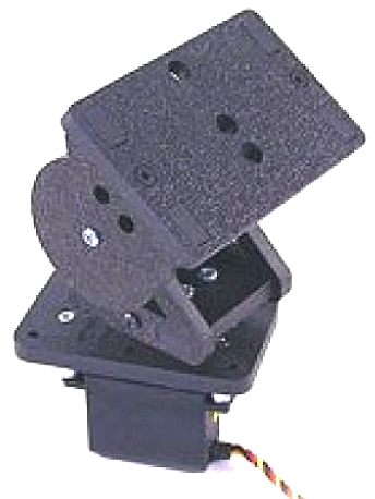
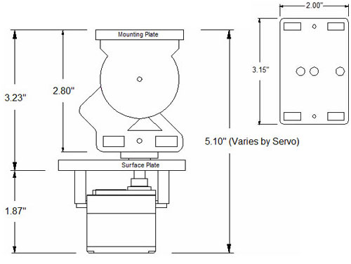
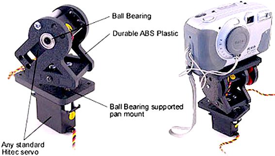
ABOVE: This is a very sturdy (and thus more expensive) ABS pan and tilt mount for up to 2lbs pounds of camera, or other equipment, weighing in at 5.5oz. Wow, that is half our budget weight to begin with. The SPT200 Direct Drive Pan & Tilt System is useful for cameras or sensors that are a bit more than hobby use. It would be far too bulky for the Scorpion HK. One of the biggest problems with servos is that they cannot always handle heavy side loads even though they may have the power to rotate your attachment. The SPT system incorporates 1/4” (6mm) shafts supported by dual ball bearings and rigid 1/4” ABS plastic which makes it one of the most rigid and precise direct drive pan and tilt available. Three 1/4” holes in the top plate make it extremely easy to mount any camera or sensor. This plate can also be easily drilled to accept other attachments. The Direct Drive Pan & Tilt System can use any standard size Hitec servo. For cameras up to 1 lb, the HS-645MG Servo Motor or the HS-485HB Servo Motor work well.
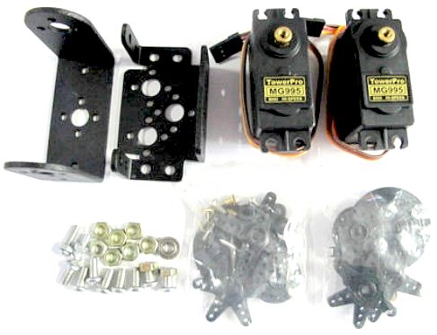
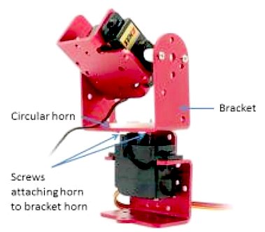
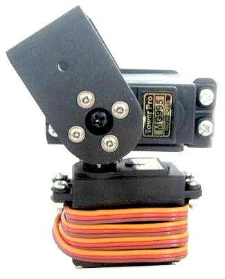
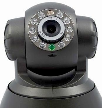
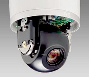
ABOVE: More examples of pan and tilt brackets, this time in ally. BELOW: Some nice looking commercially available camera pan and tilt mechanisms + a desktop missile launcher with USB connections to a computer. This is to launch projectiles at office mates - just a bit of fun.
RADIO CONTROL & ROBOTICS - A QUICK REMINDER
Radio waves are so commonly used today that many people forget they could not live without it. For example, your mobile phone is in effect a high powered radio receiver and transmitter. In fact, mobile phone apps are used to fly quite a few drone helicopters. Ships at sea reply on GPS, which is a radio signal. Security depends on encryption of that radio signal. That's it. It is that simple. But high levels of encryption slow down the actioning of a command, and that delay is called latency. Nearly all ships today use GPS for navigate. Latency in a conventional ship is the delay from thinking time of the crew. If you cut out the middle man, and go from GPS signal direct to autopilot steering, a ship will react quicker to any situation. And that is why drone, or robotic battleships will always have the advantage. Other advantages to not having a crew on board is that a robot ship is expendable, and is lighter than a manned equivalent. Guglielmo_Marconi was the father of radio, transmitting up to 6 kilometers in 1896, with an improvement patent in 1897.
GIMBALLS, PAN, TILT and ZOOM (PTZ)
Most pan and tilt systems are basically the same in that two motorized heads are parked one on top of the other, with one being fixed to a larger immovable surface, such as a building, or a mobile unit such as an airplane (usually a drone) or ship. Pan and tilt is thus similar to a gimbal movement.
A gimbal is a pivoted support that allows the rotation of an object about a single axis. A set of three gimbals, one mounted on the other with orthogonal pivot axes, may be used to allow an object mounted on the innermost gimbal to remain independent of the rotation of its support (e.g. vertical). For example, on a ship, the gyroscopes, shipboard compasses, stoves, and even drink holders typically use gimbals to keep them upright with respect to the horizon despite the ship's pitching and rolling. We need to keep missiles aimed at potential enemies, rather than horizontal, but the principle movement is similar. The challenge is to keep the sensors pointing skyward.
PTZ is an abbreviation for pan, tilt and zoom and reflects the movement options for a camera that may be used to make movies. There is no need for zoom with a gun turret or missile platform, but you may refer to the tracking medium as having a kind of zoom function, where a PTZ program is close to other methods used to identify movement and then focus on that movement - in other words targeting a moving object before firing a missile.
An innovation to PTZ cameras used in the film industry is a built-in firmware program that monitors the change of pixels generated by the video clip in the camera. When the pixels change due to movement within the cameras field of view, the camera can actually focus on the pixel variation and move the camera in an attempt to center the pixel fluctuation on the video chip. This process results in the camera following movement. The program allows the camera to estimate the size of the object which is moving and distance of the movement from the camera. With this estimate, the camera can adjust the cameras optical lens in and out in an attempt to stabilize the size of pixel fluctuation as a percentage of total viewing area. Once the movement exits the cameras field of view, the camera automatically returns to a pre-programmed or "parked" position until it senses pixel variation and the process starts over again. For military use far higher precision is needed allied to object recognition, which is all down to the programmers and their algorithms.
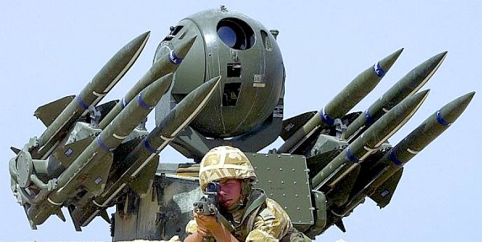
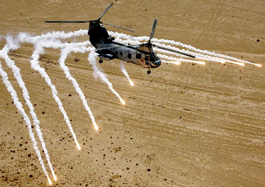
HARDKILL COUNTERMEASURES- A naval version of the Rapier SAM system may provide the all round capabilities that BMS are looking for in a comprehensive Scorpion HK weapons system. It is important to be able to neutralize attacks from manned fighter aircraft, helicopters, cruise missiles and airborne drones. This is termed a Hard Kill countermeasure, one that destroys incoming threats, as opposed to Soft Kill countermeasures, that aim to fool an incoming threat into steering away from the intended target.
LASER SIGHTING, CANNON and CAMERAS
Once the SAM turret is mechanically sorted for radio control, we might them begin to consider adding a camera and laser diode to each station, so that we can see where our missiles are aiming remotely. While we are about it, why not make the laser powerful enough to sink a competitor's vessel. Especially as our drone destroyer is electrically powered from nature, so firing a laser costs very little from the onboard energy storage banks. Guidance with this setup is thus (line of sight) remotely with a human operator. It only needs a computer onboard and a few hundred lines of code to turn such a system into a fully functional guided package. For the real deal, commercial welding lasers of 5kW can be combined in multiples to give 30 to 60kW of serious hole punching power, to thwart overhead drones or pirates that are stupid enough to come close for a high frequency toasting. We hasten to add, not the pirates themselves, their boats, which let's be honest, will go down with just one well aimed blast from such a weapon - no noise or fuss. That saves the SAMs for more serious attackers. If you have a turret onboard that is scanning the skies, you might as well multitask with it.
MILITARY GUIDANCE SYSTEMS
Missile guidance refers to a variety of methods of guiding a missile
to its intended target. The missile's target accuracy is a critical factor for its effectiveness. Guidance systems improve missile accuracy by improving its "Single Shot Kill Probability" (SSKP),
part of combat survivability calculations associated with a salvo combat model.
SOFTKILL
COUNTERMEASURES - Softkill countermeasures can be divided into on-board and expendable countermeasures. Whereas on-board measures are fixed on the platform to be protected, expendable measures are ejected from the platform.
GO
ONTO TARGET (GOT) SYSTEMS
COMMAND TO LINE OF SIGHT (CLOS)
The CLOS system uses only the angular coordinates between the missile and the target to ensure the collision. The missile is made to be in the line of sight between the launcher and the target (LOS), and any deviation of the missile from this line is corrected.
CLOS guidance is used mostly in short range air defense and antitank systems.
Active homing uses a radar system on the missile to provide a guidance signal. Typically electronics in the missile keep the radar pointed directly at the target, and the missile then looks at this "angle" of its own centerline to guide itself. Radar resolution is based on the size of the antenna, so in a smaller missile these systems are useful for attacking only large targets, ships or large bombers for instance. Active radar systems remain in widespread use in anti-shipping missiles, and in "fire-and-forget" air-to-air missile systems such as AMRAAM and R-77
Semi-active homing systems combine a passive radar receiver on the missile with a separate targeting radar that "illuminates" the target. Since the missile is typically being launched after the target was detected using a powerful radar system, it makes sense to use that same radar system to track the target, thereby avoiding problems with resolution or power, and reducing the weight of the missile. Semi-active radar homing (SARH) is by far the most common "all weather" guidance solution for anti-aircraft systems, both ground- and air-launched.
This is all way to complicated for 1/20th scale model simulations, but it is interesting to know how guidance systems are developed. The wargamers of today are the engineers of tomorrow.
DRONE TARGETS: FBQC - FUTURE BATTLESHIP QUADCOPTER
There is little point building a working SAM turret, if there is nothing to aim at. Companies like our ASV Global produce drone boats as targets for our Royal Navy. But we cannot afford such expense. Enter the world of model helicopters, or in this case quadcopters. You may have noticed how cheap these machines have become, with hundreds of toy shops and the likes of Maplins, selling then at prices that we can afford to use them for target practice.
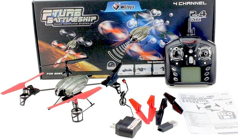
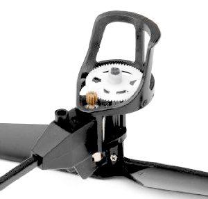
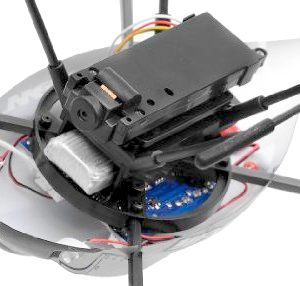
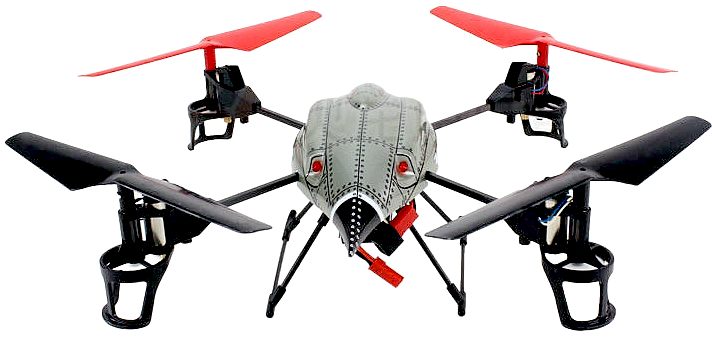
The WL Toys V959 "Future Battleship" Quadcopter (FBQC) is the perfect machine for those curious about quadcopters. Designed with simplicity in mind, and with a low mass, its flight characteristics benefit accordingly. The FBQC is constructed of durable materials, with graphite booms helping to reduce weight, so enhancing the crafts power to weight ratio. The 4 rotors are driven by 4 motors protected in plastic housings. The rotors are gear driven which relieves the stress on the small brushed motors. By all accounts the WL Toys V959 handles exceptionally well. With the help of an on board gyro and adjustable control sensitivity, the V959 is suitable for pilots of different skill level and ages.
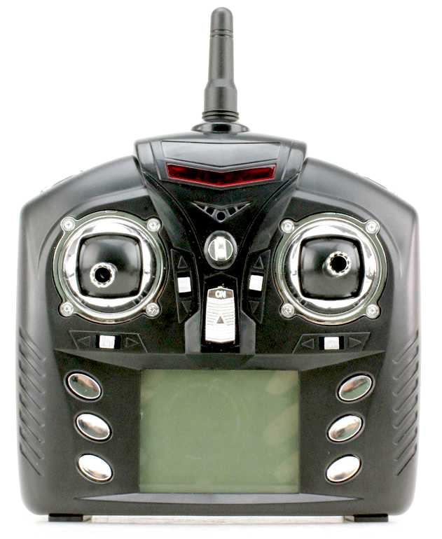
The V959 is agile, it has the ability to do flips and tricks. With the push of a button on the transmitter the aircraft will enter "trick mode" allowing the pilot to perform flips and rolls. The V959 also features LED lights that helps the pilot recognize the orientation of the helicopter and aids the pilot in low light situations. One very special feature of this V959 is the mounted spy camera on the bottom of the craft. Its adjustable lens angle allows it to be more flexible in capturing shots. The WL Toys V959 transmitter features a 2.4ghz radio system. This means you don't have to worry about signal interference and you have the ability to fly many of these at one time to be able to simulate attacks on a battleship such as the Scorpion HK.
The 'Future Battleship' drone also comes with a very basic quality camera, but this is more for fun than anything else. It takes decent pictures, but in comparison, even the most basic mobile phone offers superior picture quality. The camera can be activated via the controller, but it offers very little in the way of control or feedback.
The FBQC comes with a Gatling gun mounted on its belly, and at the flip of the switch it can rain destruction down on your family members and nosey neighbours. Well, imitation destruction at least, since the bullets are plastic, but it is one of the most exciting things about this drone. The on board gyro helps to provide a smooth flight experience. It also comes with adjustable control sensitivity, so as your experience grows, you can customize it to your preferences.
4-Ch 2.4G Remote controller
SUBMARINE INDEX
Alvin DSV - Woods Hole Oceanographic Institution Deepsea Challenger - Mariana Trench, James Cameron 2012 HMS Astute 1st of Class HMS Vanguard- Trident INS Sindhurakshak - explosion & sinking Littoral combat vessels Lusitania - Torpedo attack Nuclear submarines lost at sea Predator - Covert submarine hunter/killer Seawolf - Autonomous wolf pack deployment of Predator mini-subs Torpedoes - UUV anti submarine weapons Trieste - World record depth - Mariana Trench 1960 U20 - Kapitan Leutnant Walther Schwieger USS Bluefish WWI submarine USS Bluefish - Nuclear submarine USS Jimmy Carter - Seawolf class fast attack nuclear submarine USS Nautilus - 1st nuclear submarine & subsea north pole passage USS North Dakota - 11th Virginia class submarine USS Scorpion - Lost at sea with all hands
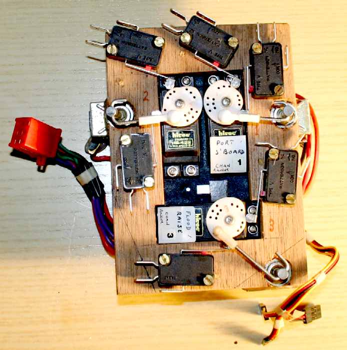
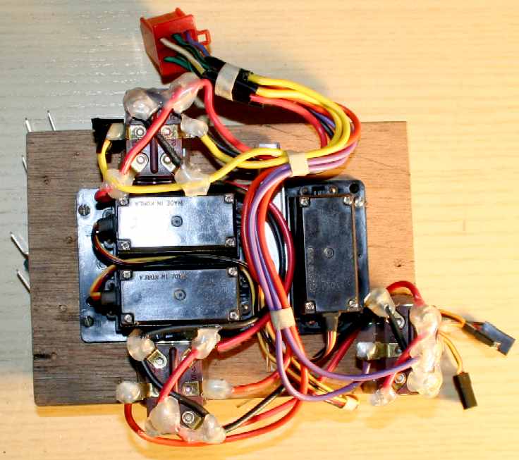
R/C servos can be used imaginatively to perform complex tasks, for example to stabilise a model ship, without the need for electronics. The simple triple servo pack shown above from 1996, was a prototype, with the rotational heads shaped into cams to form limit switches, linked to a third, dual pole (or reversing) switch, this was wired to tilt switches - to keep a model boat perfectly upright, or horizontal at sea (or in a test tank) by pumping water in and out of tanks in the hull - even where float height was a variable for a swath design, that an operator could control remotely from the shore via the same pumps, used to control horizontal attitude. This was for the first truly "active" hull in history, but the feature was never publicized as such, in accordance with patent law, such that patent protection could have been applied for. This example is now a museum exhibit.
BLUEFISH DEVELOPMENT PROJECT INDEX A-Z
SEANET™ DRONE LAYOUT - A hammerhead Scorpion HK destroyer is shown here fitted with 4 x SAM turrets (one per quadrant with independent targeting), for 360 degree multiple cover. Each SAM turret carries 8 missiles (Rapier example), giving a battery of 32 rockets to fend off enemy aircraft. This micro battleship is also shown here with 4 Tomahawk cruise missiles in protected bays, fore and aft, and 4 x 21" MK48 torpedoes in the outriggers - all drawn to scale - as a prelude to proof of concept. The torpedoes and cruise missiles would not be visible, but we've shown them in x-ray. The OAL of this clever design in 1/20th scale is 2.64m or 8 feet 7 inches. This original concept vessel is design copyright © BMS Ltd 2014.
UK ROCKET ASSOCIATION
The United Kingdom Rocketry Association (UKRA) represents high power, mid power, model and amateur/experimental rocketry in the United Kingdom. UKRA is also the specialist body to the BMFA with responsibilities for High Power Rocketry.
USA ROCKET ASSOCIATION
Model rocketry was developed during the “space race” era as an alternative to the amateur rocket activity — involving metallic airframes and the mixing of dangerous propellants — that was responsible for injuring and even killing numerous young scientific experimenters.
MODEL ROCKET SAFETY CODE - August 2012
1. Materials. I will use only lightweight, non-metal parts for the nose, body, and fins of my rocket.
2. Motors. I will use only certified, commercially-made model rocket motors, and will not tamper with these motors or use them for any purposes except those recommended by the manufacturer.
3. Ignition System. I will launch my rockets with an electrical launch system and electrical motor igniters. My launch system will have a safety interlock in series with the launch switch, and will use a launch switch that returns to the “off” position when released.
4. Misfires. If my rocket does not launch when I press the button of my electrical launch system, I will remove the launcher’s safety interlock or disconnect its battery, and will wait 60 seconds after the last launch attempt before allowing anyone to approach the rocket.
5. Launch Safety. I will use a countdown before launch, and will ensure that everyone is paying attention and is a safe distance of at least 15 feet away when I launch rockets with D motors or smaller, and 30 feet when I launch larger rockets. If I am uncertain about the safety or stability of an untested rocket, I will check the stability before flight and will fly it only after warning spectators and clearing them away to a safe distance. When conducting a simultaneous launch of more than ten rockets I will observe a safe distance of 1.5 times the maximum expected altitude of any launched rocket.
6. Launcher. I will launch my rocket from a launch rod, tower, or rail that is pointed to within 30 degrees of the vertical to ensure that the rocket flies nearly straight up, and I will use a blast deflector to prevent the motor’s exhaust from hitting the ground. To prevent accidental eye injury, I will place launchers so that the end of the launch rod is above eye level or will cap the end of the rod when it is not in use.
7. Size. My model rocket will not weigh more than 1,500 grams (53 ounces) at liftoff and will not contain more than 125 grams (4.4 ounces) of propellant or 320 N-sec (71.9 pound-seconds) of total impulse.
8. Flight Safety. I will not launch my rocket at targets, into clouds, or near airplanes, and will not put any flammable or explosive payload in my rocket.
9. Launch Site. I will launch my rocket outdoors, in an open area at least as large as shown in the accompanying table, and in safe weather conditions with wind speeds no greater than 20 miles per hour. I will ensure that there is no dry grass close to the launch pad, and that the launch site does not present risk of grass fires.
10. Recovery System. I will use a recovery system such as a streamer or parachute in my rocket so that it returns safely and undamaged and can be flown again, and I will use only flame-resistant or fireproof recovery system wadding in my rocket.
11. Recovery Safety. I will not attempt to recover my rocket from power lines, tall trees, or other dangerous places.
RADIO CONTROL ROCKET GLIDER SAFETY CODE - Revised January, 1998
The following code is to be used in conjunction with the NAR
Model Rocket Safety Code and High Power Rocket Safety Code. In areas where the R/C RBG code overlaps these other codes, the
Definition. A Radio-Controlled (R/C) Rocket Boosted Glider (RBG) is defined as a rocket boosted model capable of gliding flight and equipped with a radio control system capable of controlling the direction of flight during glide and, optionally, boost.
Radio Control.
I will use only approved radio equipment operating on frequencies allocated for use in flying models. I
will check the radio and reception range of any new model, repaired model, or any new combination of model and radio
system. I will only fly if the radio system is operating
Flightworthiness. I will check that the model is in safe and controllable condition for glide as well as in proper trim for rocket boost before each flight. I will not fly in the presence of spectators until I can safely boost, fly, and land models of the type I am flying.
Motor Thrust. My R/C RBG will weight no more than the motor manufacturer’s recommended maximum lift-off weight for the motors when used in R/C RBGs.
Launch Angle. An R/C RBG may be launched at angles of 30 to 45 degrees from vertical provided that it is capable of having its flight path controlled safely during rocket boost and provided that the launcher is pointed away from specified spectator areas. Otherwise the R/C RBG may not be launched at an angle exceeding 30 degrees from vertical.
Air-starts. During stable, gliding flight of the R/C RBG, an attached motor may be air-started to increase the model’s altitude or airspeed without diving. This is permitted if:
a) The onboard R/C ignition system is designed to not to be triggered accidentally, possesses an arm/disarm system, and is not armed until the model is on the pad with the radio system turned on and verified.
b) The proposed airstart was reviewed and approved by the Range Safety Officer (if present) prior to launch.
d)
The model is at least 100 feet above the launch site. e)
The pilot gives a loud countdown for the air-start.
Launch. The pilot will verify the glider’s radio system and
transmitter are turned on, in the desired configuration, and working prior to signaling the Launch Control Officer (LCO) the
model is ready for launch. The LCO will coordinate with the pilot when to launch the model, remaining alert to possible
calls from the pilot for the count to be stopped. Pilots may launch their models with their own launch controller if the LCO
agrees. In the event of an apparent misfire, the pilot should
NAR CONTACTS
BRITISH
MODEL FLYING ASSOCIATION
LINKS & REFERENCE
Robots tockpile wl-toys-v959-quadcopter-future-battleship-gatling-machine-gun-with-onboard-camera PT boat contra rotating electric torpedo The
Guardian June 2003 Terrorism David Fickling Aardvark
DIY cruise missiles Hackaday 2010 diy guided missile err model rocket Sites google airwavershr guided rocket Wikipedia Pan tilt zoom_camera Raspberry pi spy pan and tilt mechanism for the raspberry camera National Association of Rocketry British Model Flying Association https://www.bmfa.org/ http://www.nar.org/ http://www.ukra.org.uk/ http://en.wikipedia.org/wiki/MIM-3_Nike_Ajax http://en.wikipedia.org/wiki/Pan%E2%80%93tilt%E2%80%93zoom_camera http://www.raspberrypi-spy.co.uk/2013/09/pipan-pan-and-tilt-mechanism-for-the-raspberry-pi-camera/ http://en.wikipedia.org/wiki/Servo_%28radio_control%29 https://sites.google.com/site/airwavershr/Home/guided-rocket http://hackaday.com/2010/08/03/diy-guided-missile-err-model-rocket/ http://www.subcommittee.com/ http://www.rc-submarines.net/torpedoes.html http://www.pt-boat.com/torpedo/torpedo.html
|
|||||||||||||||||||||||||||||||||||||||||||||||||||||||||||||||||||||||||||||||||||||||||||||||||||||||||||||||||||||||||
|
This website is Copyright © 2014 Bluebird Marine Systems Ltd. The names Bluebird™, Bluefish™, SeaNet™, SeaWolf™ and the blue bird and fish in flight logos are trademarks. CONTACTS The color blue is a protected feature of the trademarks.
|
|||||||||||||||||||||||||||||||||||||||||||||||||||||||||||||||||||||||||||||||||||||||||||||||||||||||||||||||||||||||||