|
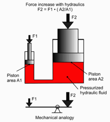
LEVERAGE
- The
most fundamental principle of hydraulics is the mechanical advantage obtained by
multiplying the input pressure applied piston (F1) by the output pressure load
(F2). The mechanical analogy is a simple lever and fulcrum.
BASICS
Hydraulic machines
use liquid fluid power to do simple work. Heavy equipment such as earth movers
and diggers (JCBs) are common examples.
In this type of machine, hydraulic fluid is transmitted throughout the machine to various hydraulic motors and hydraulic cylinders and which becomes
pressurized according to the resistance present. The fluid is controlled directly or automatically by control valves and distributed through hoses and tubes.
The popularity of hydraulic machinery is due to the very large amount of power that can be transferred through small tubes and flexible hoses, and the high power density
(10 x electric motors) and wide array of actuators that can make use of this power.
The disadvantage is that a system may not be as energy efficient as a direct
mechanical drive. Certainly, this general rule applies to land vehicles,
although every effort is being made to improve the efficiency of hydraulics
wheel-motors.
Hydraulic machinery is operated by the use of hydraulics, where a liquid is the powering
medium and valves are used to allow the flow of fluid, usually in two opposing
directions (power and return stroke) along a common axis, with the valve being
used to direct fluid flow as desired.
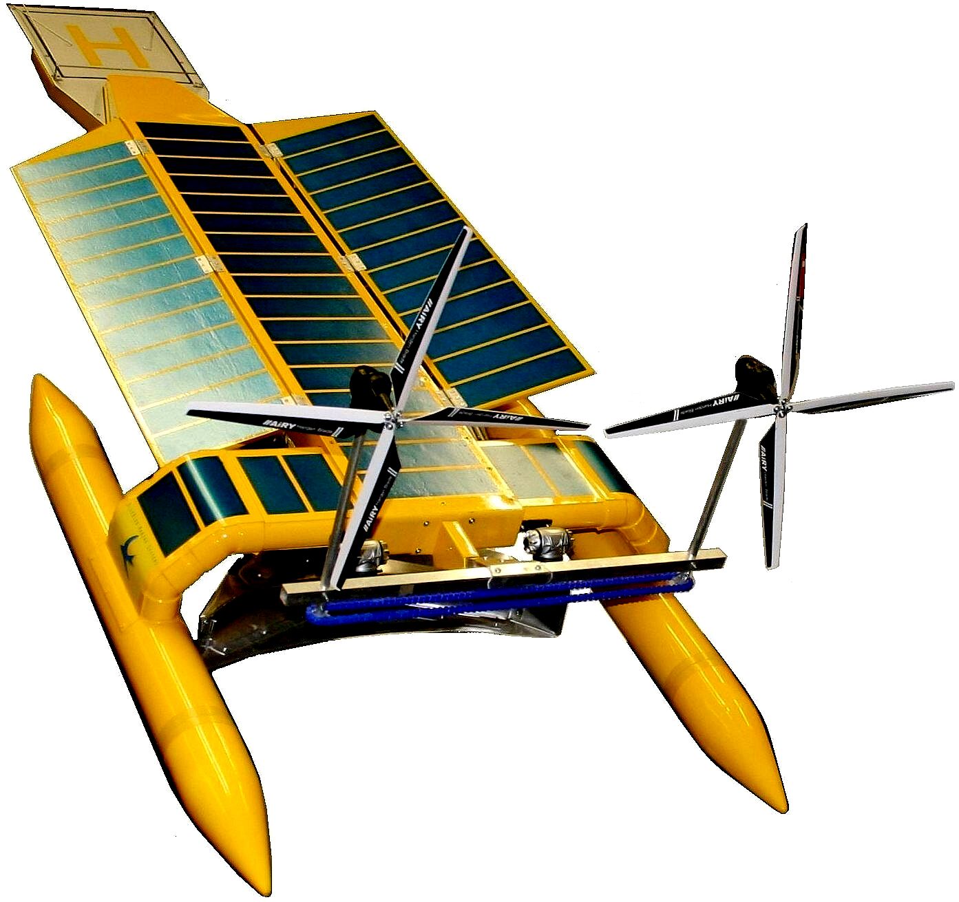
SEAVAX:
Potentially, the ocean garbage (plastic) pollution solution and
more - this environmental cleanup machine uses a mix of hydraulics to
perform its functions efficiently, including pumps, cylinders and rotary motors.
Electric actuators could perform many of the same functions, but the reason for
using hydraulics is flexibility and concentrated power just where it is needed.
Linear movement is perhaps one of the easiest to achieve using hydraulics and to
use that force conveniently, such as in the jack that lifts a heavy car at very
little exertion to the operator.
ROBOTICS
Hydraulics
in robotics is not that usual, where robots typically use pneumatic cylinders,
or electric servos. Where SeaVax is concerned, hydraulics is a good idea because
of the high reliability and adaptability to our purposes.
SYSTEM
COMPONENTS
HYDRAULIC PUMP
Hydraulic pumps supply fluid to the components in the system. Pressure in the system develops in reaction to the load. Hence, a pump rated for 5,000 psi is capable of maintaining flow against a load of 5,000 psi.
Pumps have a power density about ten times greater than an electric motor (by volume). They are powered by an electric motor or an engine, connected through gears, belts, or a flexible elastomeric coupling to reduce vibration.
Common types of hydraulic pumps to hydraulic machinery applications are;
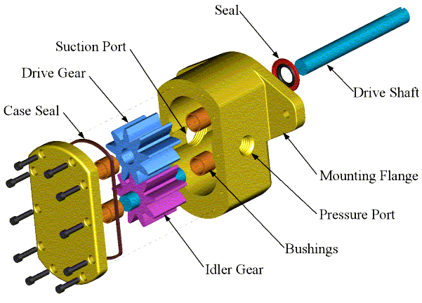
1. Gear pump: cheap, durable (especially in g-rotor form), simple. Less efficient, because they are constant (fixed) displacement, and mainly suitable for pressures below 20 MPa (3000
psi).
2. Vane pump: cheap and simple, reliable. Good for higher-flow low-pressure output.
3.
Axial piston pump: many designed with a variable displacement mechanism, to vary output flow for automatic control of pressure.
There are various axial piston pump designs, including swashplate (sometimes referred to as a valveplate pump) and checkball (sometimes referred to as a wobble plate pump). The most common is the swashplate pump. A variable-angle swashplate causes the pistons to reciprocate a greater or lesser distance per rotation, allowing output flow rate and pressure to be varied (greater displacement angle causes higher flow rate, lower pressure, and vice versa).
4.
Radial piston pump: normally used for very high pressure at small flows.
Piston pumps are more expensive than gear or vane pumps, but provide longer life operating at higher pressure, with difficult fluids and longer continuous duty cycles. Piston pumps make up one half of a hydrostatic transmission.
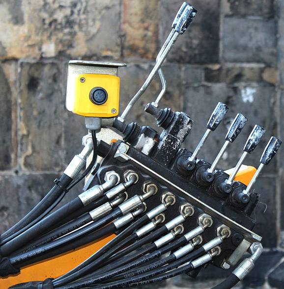
A
manually operated lever control console. Not really applicable to robotics, save
where the vessel may be controlled optionally by a crew. For a pre-production
prototype this is a good developmental stage.
CONTROL VALVES
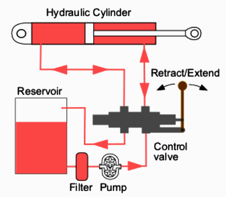
Directional control valves route the fluid to the desired actuator. They usually consist of a spool inside a cast iron or steel housing. The spool slides to different positions in the housing, and intersecting grooves and channels route the fluid based on the spool's position.
The spool has a central (neutral) position maintained with springs; in this position the supply fluid is blocked, or returned to tank. Sliding the spool to one side routes the hydraulic fluid to an actuator and provides a return path from the actuator to tank. When the spool is moved to the opposite direction the supply and return paths are switched. When the spool is allowed to return to neutral (center) position the actuator fluid paths are blocked, locking it in position.
Directional control valves are usually designed to be stackable, with one valve for each hydraulic cylinder, and one fluid input supplying all the valves in the stack.
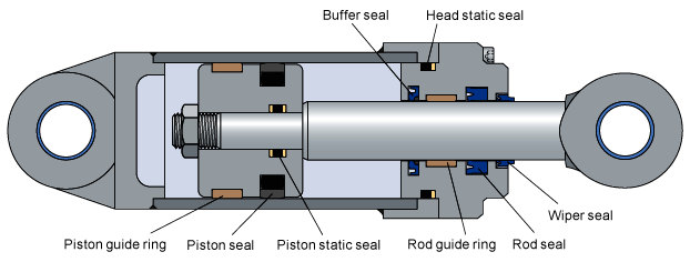
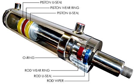
Cutaway
diagrams of hydraulic cylinder actuators showing the working component parts.
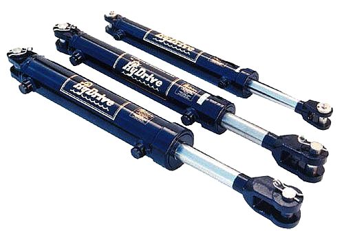
Hydraulic
rams as used to steer boats and as part of an autopilot navigation system. These
heavy-duty cylinders from Hydrive have hard-chromed 316 stainless steel piston rods.
They are polyurethane coated for high protection against the environment and
have stainless steel clevis pins and fittings.
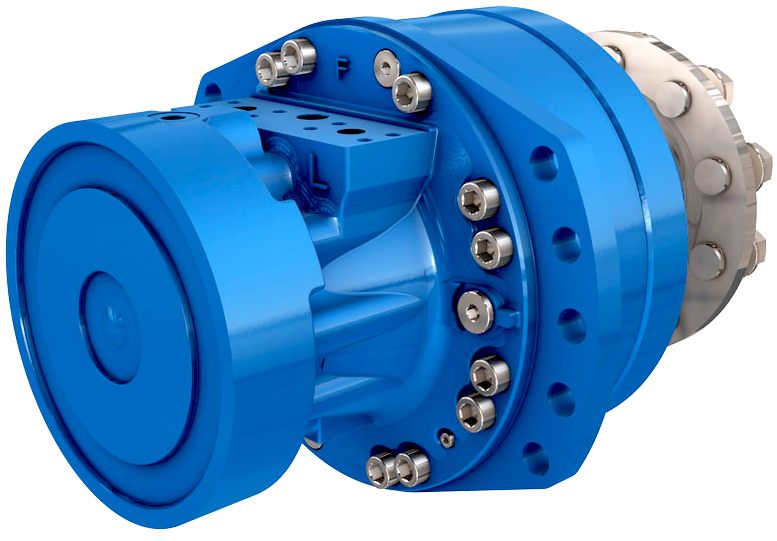
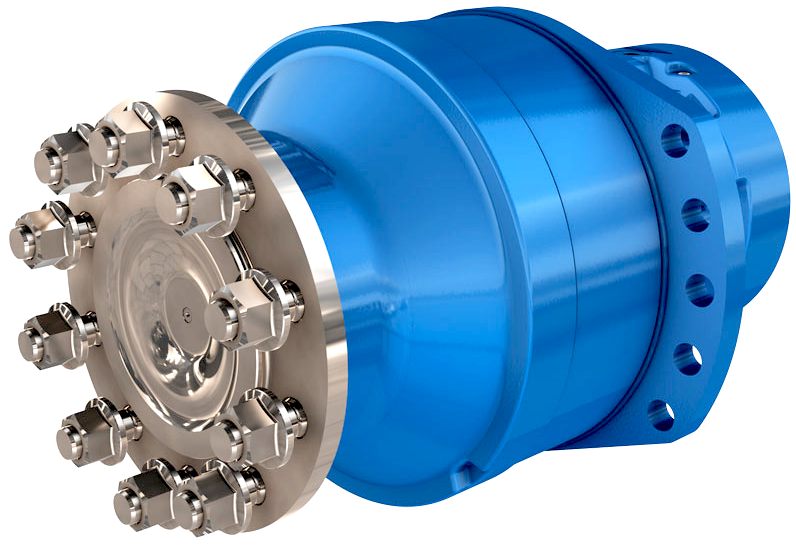
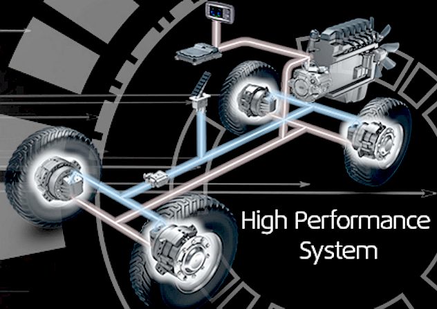
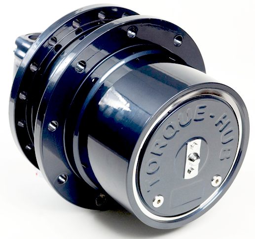
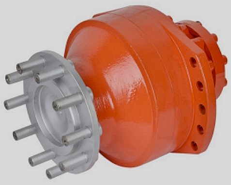
DRIVING
FORCE - This is a selection of off-the-shelf hydraulic wheel motors,
most of which we could use for the AmphiVax™ launch & recovery
vehicle. These are wheel hubs with a fluid motor drive inboard of the
wheel mounting flange. Rotary hydraulic drives solve a lot of transmission
problems.
Tolerances are very tight in order to handle the high pressure and avoid leaking, spools typically have a clearance with the housing of less than a thousandth of an inch (25 µm). The valve block will be mounted to the machine's frame with a three point pattern to avoid distorting the valve block and jamming the valve's sensitive components.
The spool position may be actuated by mechanical levers, hydraulic pilot pressure, or solenoids which push the spool left or right. A seal allows part of the spool to protrude outside the housing, where it is accessible to the actuator.
The main valve block is usually a stack of off the shelf directional control valves chosen by flow capacity and performance. Some valves are designed to be proportional (flow rate proportional to valve position), while others may be simply on-off. The control valve is one of the most expensive and sensitive parts of a hydraulic circuit.
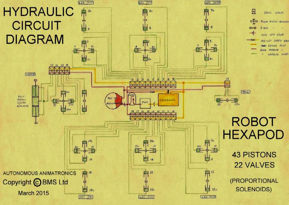
The
above is a complex circuit diagram for a hexapod robot, involving the operation
of 43 pistons, using 22 valves. In this case the valves will be computer
controlled and electrically operated. Imagine that the above diagram is not for
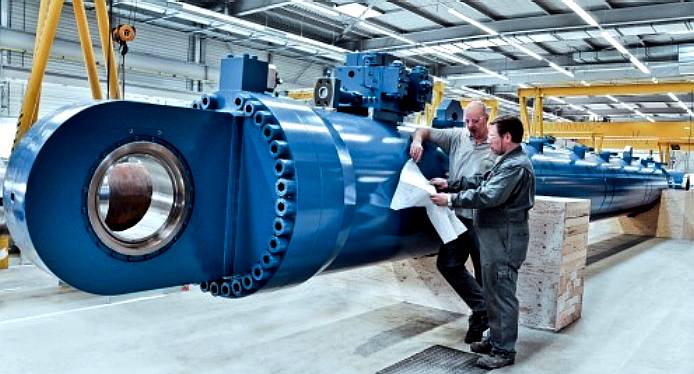
a 2.5 meter robot for use in movie animation, but one of the giant defenders in Pacific
Rim, in which case the rams might be as big as that below.
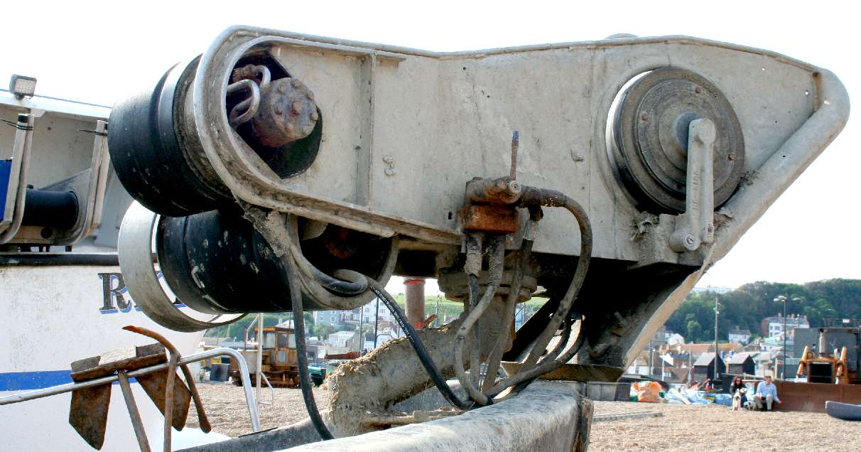
NET
WINCH - Many fishing boats use hydraulically powered winches to recover
their catch. This is because it is relatively easy to fit a pump on their diesel
engines that can then be used for fishing instead of propelling the vessel. Once
the catch is safely landed, at the flick of a lever, they can transfer the
energy from the engine to propulsion again.
HYDRAULIC CYLINDER
A Hydraulic cylinder (also called a linear hydraulic motor) is a mechanical actuator that is used to give a unidirectional force through a unidirectional stroke. It has many applications, notably in construction equipment (engineering vehicles), manufacturing machinery, and
civil
engineering.
Hydraulic cylinders get their power from pressurized hydraulic fluid, which is typically oil. The hydraulic cylinder consists of a cylinder barrel, in which a piston connected to a piston rod moves back and forth. The barrel is closed on one end by the cylinder bottom (also called the cap) and the other end by the cylinder head (also called the gland) where the piston rod comes out of the cylinder. The piston has sliding rings and seals. The piston divides the inside of the cylinder into two chambers, the bottom chamber (cap end) and the piston rod side chamber (rod end / head end).
Flanges, trunnions, clevises, Lugs are common cylinder mounting options. The piston rod also has mounting attachments to connect the cylinder to the object or machine component that it is pushing / pulling.
A hydraulic cylinder is the actuator or "motor" side of this system. The "generator" side of the hydraulic system is the hydraulic pump which brings in a fixed or regulated flow of oil to the hydraulic cylinder, to move the piston. The piston pushes the oil in the other chamber back to the reservoir. If we assume that the oil enters from cap end, during extension stroke, and the oil pressure in the rod end / head end is approximately zero, the force F on the piston rod equals the pressure P in the cylinder times the piston area A: F = P
. A
Youtube
LINKS
& REFERENCE

Bonfiglioli UK Limited
Phone: 01925 852667
www.bonfiglioli.com


www.daihohyd.co.kr
Ningbo Bonny Hydraulics Transmission
Co Ltd
China
Tel: 86-0574-86879210

Poclain
Hydraulics Ltd
Nene Valley Business Park, Oundle, Peterborough
Cambs, PE8 4HN, United Kingdom
Tel: +44 1832 273773
Shandong Sino Metal
Co Ltd
1103, Bldg. 24, Zone 1, Mingshi Haoting, Jingshi Road, Lixia Dist, Jinan, China

Xiamen Banruo Industrial Co Ltd
Unit 10D Gongyulou Lianfu Building No. 2, Lianqian West Road, Xiamen China
Tel: 0086-592-5823971 Fax: 0086-592-5919994
Http://www.brhydraulic.com
Wikipedia
hydraulic_machinery
Power
Cylinders hydraulic-cylinders
Wikipedia
hydraulic_drive_system
Wikipedia
hydraulic_cylinder
http://www.powercylinders.in/hydraulic-cylinders.htm
http://en.wikipedia.org/wiki/Hydraulic_drive_system
http://en.wikipedia.org/wiki/Hydraulic_cylinder
http://en.wikipedia.org/wiki/Hydraulic_machinery

Bluebird
Marine Systems Ltd
Solar
House, BN27 1RF, UK +
44 (0) 1323 831727


|


