|
AMPHIBIOUS LAUNCH - AMPHIMAX - CAB - CHASSIS - DIESELS - FLOATATION - HYDRAULICS - LAUNCH SITE - MODEL 1/20 - TIMETABLE - TRACKS - TRAILER - THRUSTERS - WHEELS
|
|||||||||||||||||||||||||||||||||||||||||||||||||||||||||||||||||||||||||||||||||||||||||||
|
EIGHT AXLES - Shown here is an 8 axle (16 wheels) chassis. We've come down from 10 axles, to be practical, to drive 16 wheels as 4 hydraulic circuits, rather than 5 hydraulic circuits, that may cause imbalance in the system. This is because of the need to steer the vehicle, bearing in mind that most pumps powerful enough to power the wheel-motors have four outputs. We would then need four pumps like the Poclain PL4H10 or equivalent, that can deliver up to 33,750 litres/minute (L/M) into four outputs. The combined torque without a reduction gearbox would be 430,000Nm (43,847 kg/m or 43.8 tons/m of leverage), more than enough to climb a 20-30% slope.
EXAMPLE - Using 16 x Poclain MS25 wheel-motors (with planetary reduction) aiming for 40 rpm per wheel motor (8.7 mph) we'd need a total fluid flow of 78,272 L/M. Four PL4H10 pumps can deliver 135,000 L/M - almost twice the flow required. The power handling capacity is also well within range @ 137kW per pump unit, giving us around 510kW capacity when we only need around 300kW in theory. It might though be worth increasing the engine power for a greater reserve - and better hill climbing ability. The diagram above shows four 140kW (188hp) engines in blue, with four oil reservoirs in green. The pressure flow circuit is shown in red and the control valves are blue.
Please note that this drawing is Copyright © May 25 2017 Bluebird Marine Systems Ltd, all rights reserved. You will need permission from the company to reproduce these diagrams except for private study or review or for supplier reference.
TYPES OF HYDRAULIC PUMP
A modern hydraulic pump is a machine that converts rotary mechanical power from electric or internal combustion engines into hydraulic energy (hydrostatic energy i.e. flow, pressure). It generates flow with enough power to overcome pressure induced by the load at the pump outlet.
When a hydraulic pump operates, it creates a vacuum at the pump inlet, which forces liquid from a reservoir of fluid into the inlet line to the pump and by mechanical action delivers this liquid to the pump outlet and forces it into the hydraulic system.
Hydrostatic pumps are positive displacement pumps while hydrodynamic pumps can be fixed displacement pumps, in which the displacement (flow through the pump per rotation of the pump) cannot be adjusted, or variable displacement pumps, which have a more complicated construction that allows the displacement to be adjusted. Hydrodynamic pumps are more frequent in day-to-day life.
Hydrostatic pumps, of various designs, work on the principle of Pascal's law, which states that: the increase in pressure at one point of the enclosed liquid in equilibrium of rest is transmitted equally to all other points of the liquid, unless the effect of gravity is neglected. (in case of statics)
OPEN and CLOSED SYSTEMS
Most pumps work in open systems, where pump draws oil from a reservoir at atmospheric pressure. In such systems it is very important that there is no cavitation at the suction side of the pump. For this reason the connection of the suction side of the pump is larger in diameter than the connection of the pressure side.
In case of multi-pump assemblies, the suction connection of the pump is often combined. It is preferred to have free flow to the pump (pressure at inlet of pump at least 0.8 bars). The body of the pump is often in open connection with the suction side of the pump.
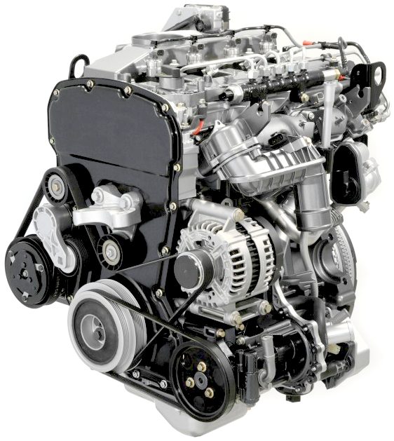
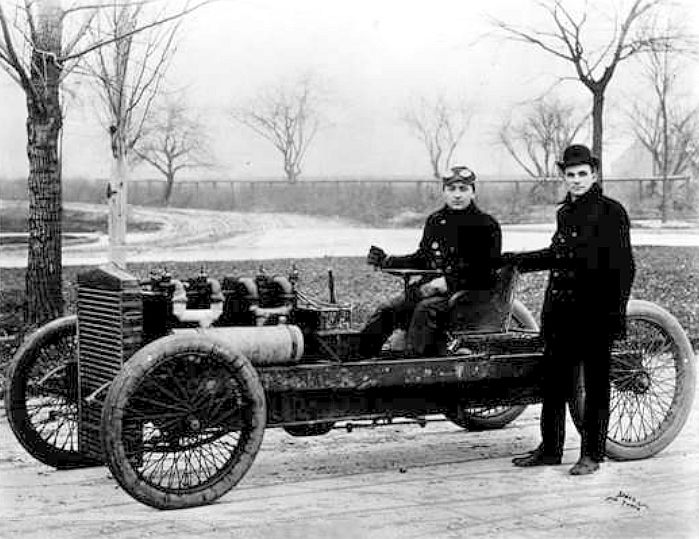
FORD DIESEL - [LEFT] This is a 3.2-liter engine from the famous car maker. It produces 197 hp and 347 lb-ft of torque in European specification with 90 percent of peak torque available from 1,700 to 3,500 rpm, just where it is needed for the AmphiMax. The inline-five diesel’s torque curve is said to be as flat as the Bonneville salt raceway. [RIGHT} It's a little known fact that on January the 4th 1912, Henry Ford set a land speed record on ice at 91.37 mph on the frozen surface of Michigan’s Lake St. Clair. He was driving a four-wheel vehicle, dubbed the “999,” with a wooden chassis and an upright steering wheel. We love it!
MULTI PUMP SYSTEMS
In a hydraulic installation, one pump can serve several cylinders and motors. In that case a constant pressure system is required.
Sometimes, it may be more economic to give each cylinder and motor its own pump. In that case, multi-pump assemblies can be used. Gear pumps are often supplied as multi-pumps. The different chambers (sometimes of different sizes) are mounted in one body or built together. Vane pumps and gerotor pumps are often available as multi-pumps. Screw pumps can be combined with gear or vane pumps.
Axial piston swashplate pumps can be combined with a second pump, or with one or more gear pumps or vane pumps (the gear or vane pumps often serving as flush pumps for cooling larger units). Axial plunger pumps of the bent-axis design cannot be combined with other pumps.
ELECTRO
HYDRAULIC PUMPS
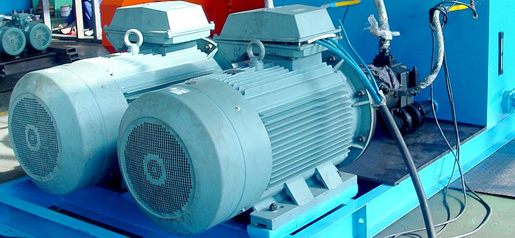
DIESEL POWER
This is commonplace today where heavy machinery is involved and we are giving it serious consideration from an economic point of view. Typically, industrial hydraulic motors for earth moving vehicles and construction equipment are powered by diesel engines.
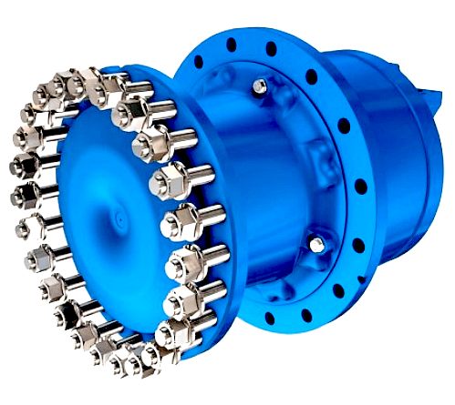
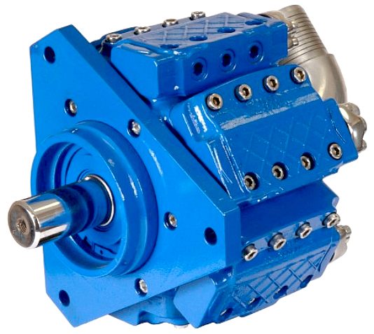
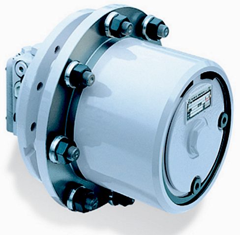
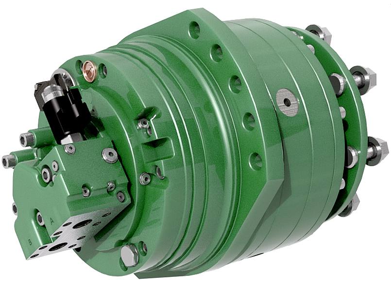
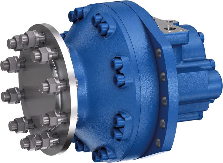
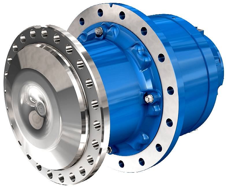
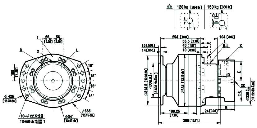
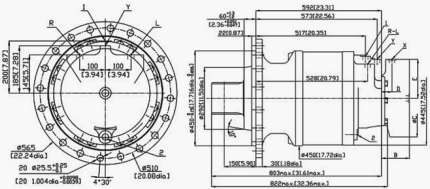
[left] POCLAIN MS125 WHEEL MOTOR - Torque Max: 23850Nm @ 100bar (12128 lb.ft at 1000 PSI). Speed Max: (RPM) 50. Power Max: 240kW (322 hp). Max Displacement cm3/rev. 15000 (Cu.in/rev. 914.9). Max. Pressure bar: 450, PSI: 6527
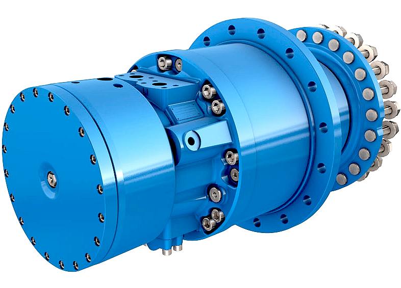
[right] POCLAIN PUMPS PL6H - Max. pressure bar 450 (PSI 6526) Max Displacement cm3/rev. 444. Max rotation speed: rpm 2000. Max power 666kW (HP 895).
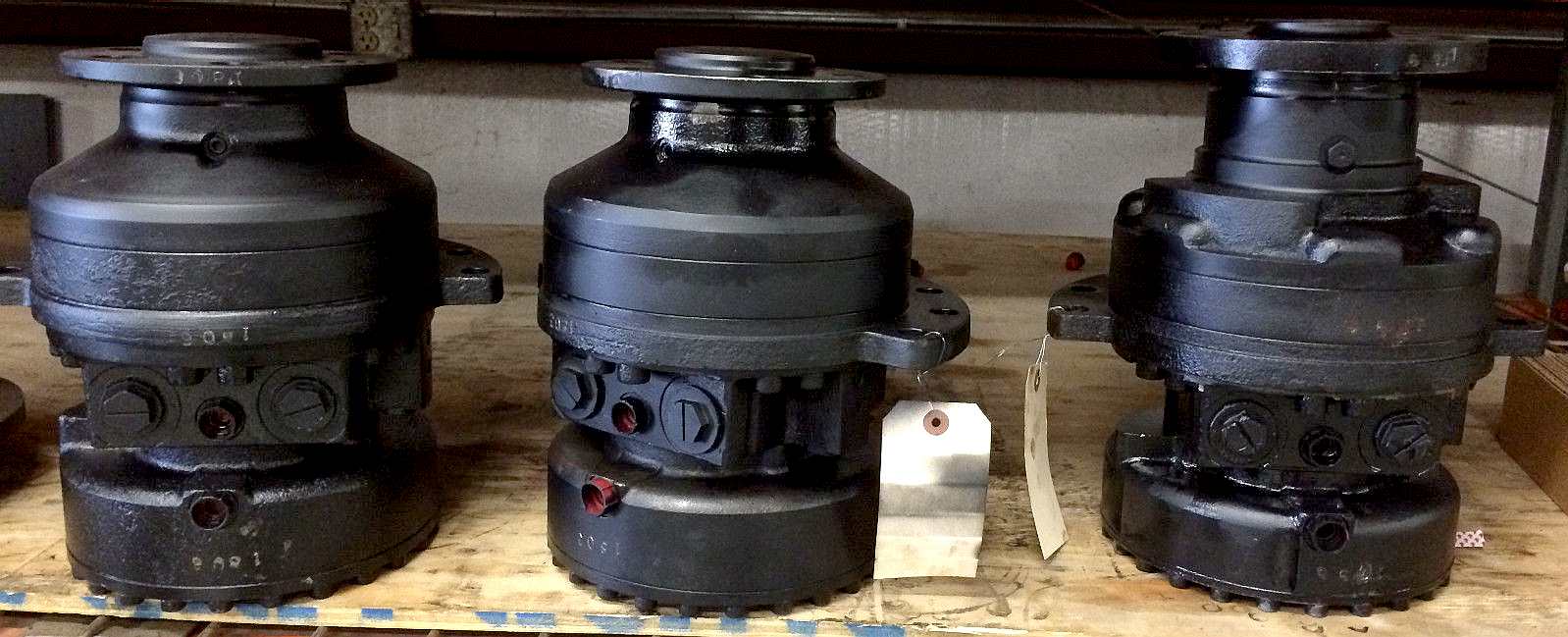
DRIVING FORCE - This is a selection of off-the-shelf hydraulic wheel motors, most of which we could use for the AmphiVax™ launch & recovery vehicle. These are wheel hubs with a fluid motor drive inboard of the wheel mounting flange. Rotary hydraulic drives solve a lot of transmission problems. They are especially popular with designers for machines used in civil engineering projects and factories.
INPUT FORCE - Turning electrical energy into fluid pressure using pumps. The operating pressure multiplied by the volumetric capacity determines the work that can be done. These large industrial pumps power hydraulic motors for industrial uses such as drilling for oil. Hmmmmm. Not all hydraulics are used for good.
DIMENSIONS - In order to be able to design a system, you have to know the basics of the machines that are available. Most manufacturers publish this information in product brochures: Power Output, RPM, Torque, Dimensions, Weight, etc. Most frustratingly, most makers do not publish prices, making it hard to shop around to compare a Rolls-Royce, with a budget setup.
FLUID POWER FORMULAS - USEFUL REFERENCE
GEAR PUMPS - Gear pumps (with external teeth) (fixed displacement) are simple and economical pumps. The swept volume or displacement of gear pumps for hydraulics will be between about 1 and 200 millilitres. They have the lowest volumetric efficiency (Nv = 90% ) of all three basic pump types (gear, vane and piston pumps)[1] These pumps create pressure through the meshing of the gear teeth, which forces fluid around the gears to pressurize the outlet side. For lubrication, the gear pump uses a small amount of oil from the pressurized side of the gears, bleeds this through the (typically) hydrodynamic bearings, and vents the same oil either to the low pressure side of the gears, or through a dedicated drain port on the pump housing. Some gear pumps can be quite noisy, compared to other types, but modern gear pumps are highly reliable and much quieter than older models. This is in part due to designs incorporating split gears, helical gear teeth and higher precision/quality tooth profiles that mesh and unmesh more smoothly, reducing pressure ripple and related detrimental problems. Another positive attribute of the gear pump, is that catastrophic breakdown is a lot less common than in most other types of hydraulic pumps. This is because the gears gradually wear down the housing and/or main bushings, reducing the volumetric efficiency of the pump gradually until it is all but useless. This often happens long before wear causes the unit to seize or break down.
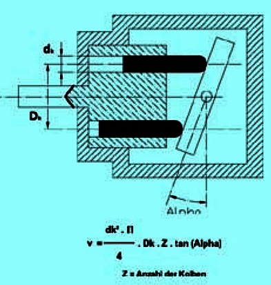
RADIAL PISTON PUMPS - Radial piston pumps are used especially for high pressure and relatively small flows. Pressures of up to 650 bar are normal. In fact variable displacement is possible. The pump is designed in such a way that the plungers are connected to a floating ring. This floating ring can be moved horizontally by a control lever & thus causes an eccentricity in the centre of rotation of the plungers. The amount of eccentricity can be controlled to vary the discharge. The suction & discharge can be totally reversed seamlessly by shifting the eccentricity to the opposite side. Hence both quantity & direction can be varied in a radial piston pump, just as in the Swash plate pump.
ROTARY VANE PUMPS - Rotary vane pumps (fixed and simple adjustable displacement) have higher efficiencies than gear pumps, but are also used for mid pressures up to 180 bar (18,000 kPa) in general. Modern units can exceed 300 bar (30,000 kPa) in continuous operation, although vane pumps are not regarded as "high pressure" components. Some types of vane pumps can change the centre of the vane body, so that a simple adjustable pump is obtained. These adjustable vane pumps are in general constant pressure or constant power pumps: the displacement is increased until the required pressure or power is reached and subsequently the displacement or swept volume is decreased until an equilibrium is reached. A critical element in vane pump design is how the vanes are pushed into contact with the pump housing, and how the vane tips are machined at this very point. Several type of "lip" designs are used, and the main objective is to provide a tight seal between the inside of the housing and the vane, and at the same time to minimize wear and metal-to-metal contact. Forcing the vane out of the rotating centre and towards the pump housing is accomplished using spring-loaded vanes, or more traditionally, vanes loaded hydrodynamically (via the pressurized system fluid).
AXIAL PISTON PUMPS & SWASHPLATES - Axial piston pumps using the swashplate principle (fixed and adjustable displacement) have a quality that is almost the same as the bent axis model. They have the advantage of being more compact in design and also allow use of "through-drive" series mounted auxiliary rotating equipment, based on their in-line design. The pumps are easier and more economical to manufacture; the disadvantage is that they are more sensitive to oil contamination. The axial piston pump is likely the most widely used variable displacement type, being found in everything from heavy industrial to mobile applications. By using different compensation techniques, the variable displacement type of these pumps can continuously alter fluid discharge per revolution and system pressure based on load requirements, maximum pressure cut-off settings, horsepower/ratio control, and even fully electroproportional systems, requiring no other input than electrical signals. This makes them potentially hugely power saving compared to other constant flow pumps in systems where prime mover/diesel/electric motor rotational speed is constant and required fluid flow is non-constant.
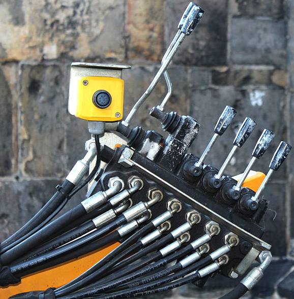
CONTROL BANK - A manually operated lever control console. We'd not use an item like this on our autonomous boats unless a customer wanted manual controls to deal with unusual situations where a robot might not yet be adapted for such use. We can train a robot using manual controls.
CONTROL VALVES
LINKS & REFERENCE
Calculate horsepower to power a hydraulic-pump External gear pump description Internal gear pump description Mechanical efficiency description Hydraulic efficiency description https://en.wikipedia.org/wiki/Hydraulic_pump http://www.engineeringtoolbox.com/hydraulic-pumps-horsepower-d_1464.html Wikipedia hydraulic_drive_system http://en.wikipedia.org/wiki/Hydraulic_drive_system http://en.wikipedia.org/wiki/Hydraulic_cylinder http://en.wikipedia.org/wiki/Hydraulic_machinery
AMPHIBIOUS LAUNCH - AMPHIMAX - CAB - CHASSIS - DIESELS - FLOATATION - HYDRAULICS - LAUNCH SITE - MODEL 1/20 - TIMETABLE - TRACKS - TRAILER - THRUSTERS - WHEELS
|
|||||||||||||||||||||||||||||||||||||||||||||||||||||||||||||||||||||||||||||||||||||||||||
|
This page is Copyright © 2016 Bluebird Marine Systems Ltd. The names AmphiMax™, Bluebird™, Bluefish™, RiverVax™, SeaNet™, SeaVax™ and the blue bird & fish in flight logos are trademarks. All other trademarks are hereby acknowledged.
|
|||||||||||||||||||||||||||||||||||||||||||||||||||||||||||||||||||||||||||||||||||||||||||