|
SEAVAX - WATER TANK SLUICE GATE
BRICKS & MORTAR - CARRIAGE - DRAINAGE - FACILITIES - FILTRATION - GLASS & PAINT - GANTRY - GIMBALS - HATCHES - HYDRODYNAMICS HISTORY - INSTRUMENTS - LABORATORY - LAMINATING - LOGISTICS - OUR TEST TANK - PROOFING - REVIEWS - SCREEDING - SEAVAX TEST VIDEOS - SLUICE GATE - SOLAR BATTERIES - WAVE MAKING - WIND MACHINE
|
||
|
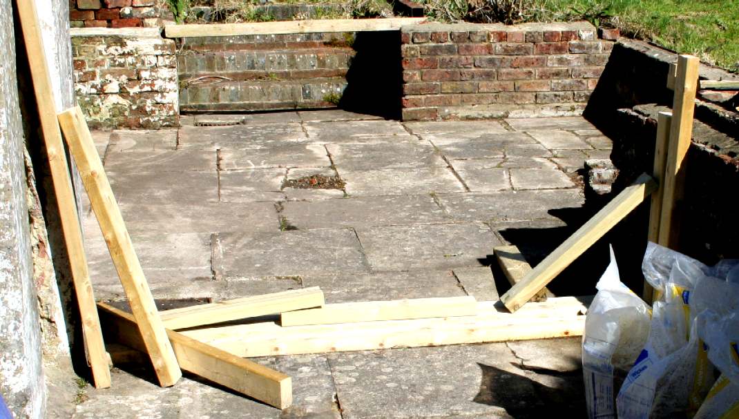
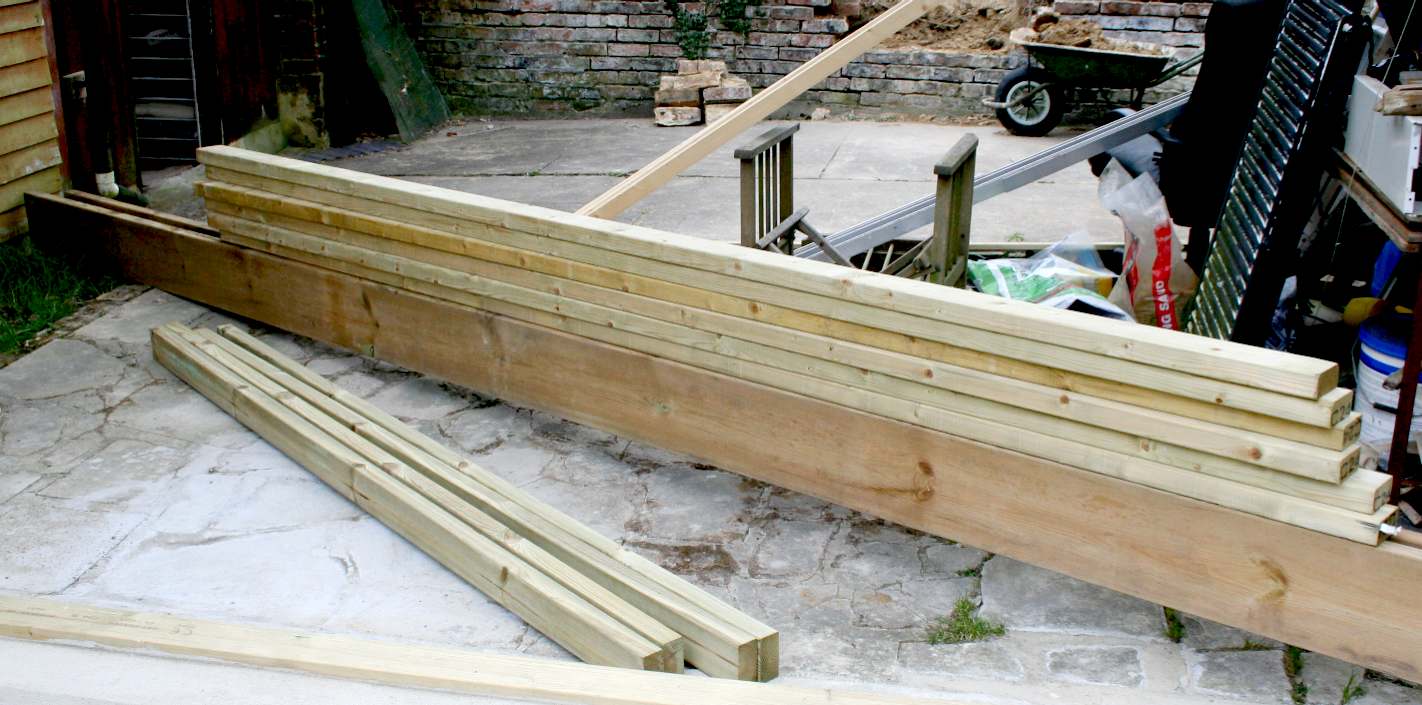
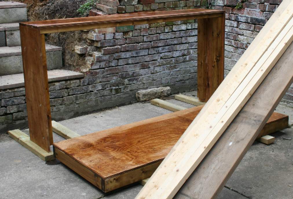
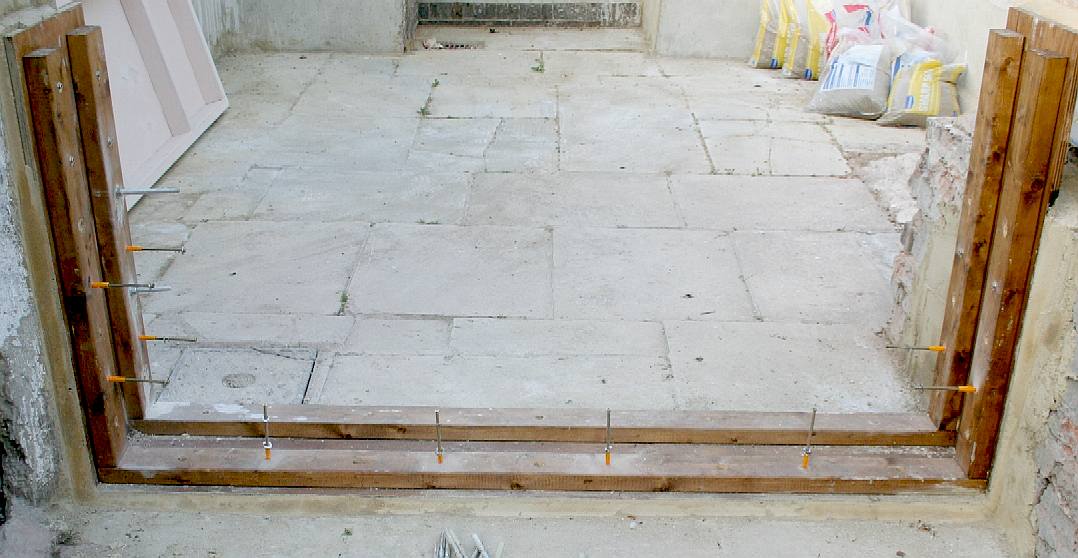
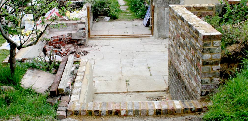
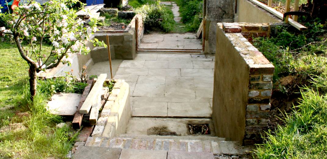
SITE CLEARING - This is an ideal location for a private test tank facility. There are two convenient drains for emptying and steps to allow for easy launching of the SeaVax and other ship models. The brick walls will need to be rendered up to a height of about 750mm. The cracks in between the stone slabs will be caulked, but they are laid on stabilized clay - and clay is the material of choice for a pond liner. This sub-surface area is seen in the diagram (plan view) below on the far right, shaded in blue. The timber in the foreground is the cut parts for the frame of the sluice gate that closes this end to contain the water.
In order to turn this subsurface courtyard into a water tank, we need to install a barrier on the open end facing us in the picture above. We could do this with another brick or block wall, but that would not give us so many options - and we need flexibility.
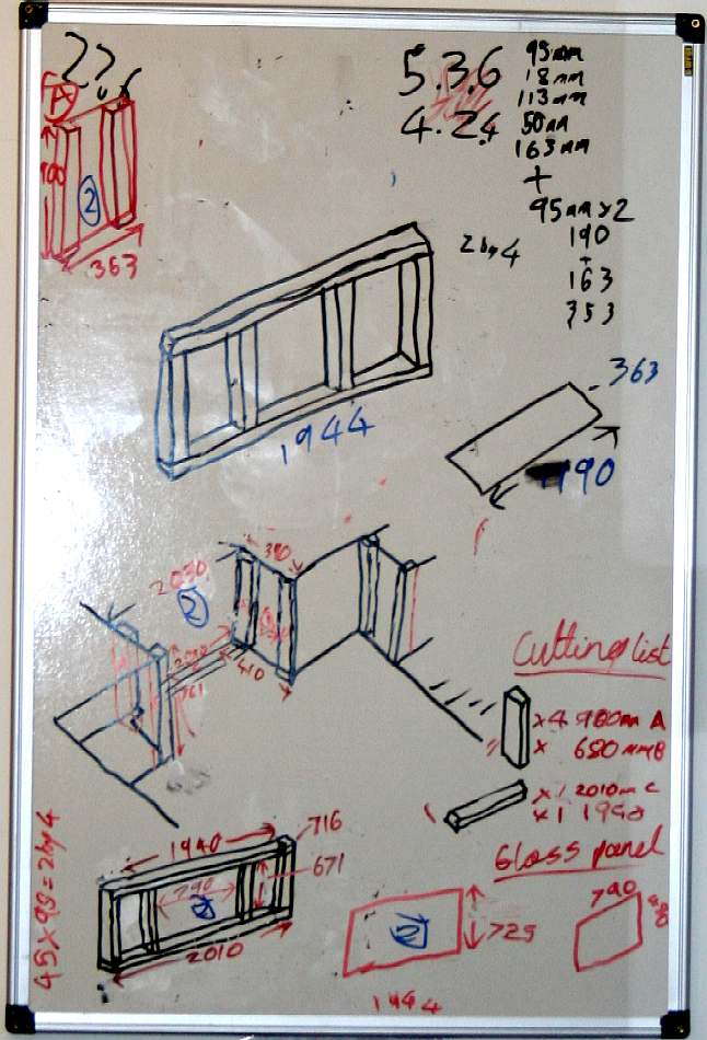
PLAN VIEW - This plan view is of the overhead beams of a stainless steel gantry. You can also see the sluice gate in red on the left. The gantry is a stainless steel "T" beam with a four wheel bogie that supports a cross-beam, also of "T" section stainless steel.
DAMS
As with any man made dam, the gate has to be strong enough to hold back water pressure, almost a ton of it. It is not only the gate that needs to be tough, but also the frame that bolts to the walls on either side and the floor.
A dam is thicker at the bottom than at the top, because the pressure against the wall increases with depth. The pressure bearing down on the floor of our water tank is a simple calculation. Water weighs 62.4 pounds per cubic foot, or 1000kg per cubic meter. If our tank is approximately 188 square feet (17.43m), then for every foot of water depth the total floor area will have to support 11,738 lbs. When two feet deep the floor will need to support 23,738lbs and when filled to 2.5 feet: 29,345lbs (13.1 imperial tons or 13,310.7kg).
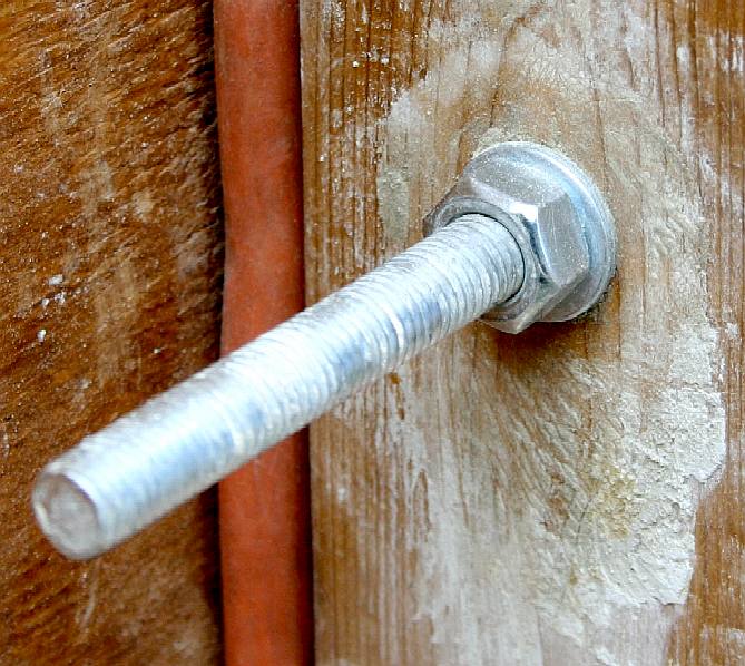
When calculating pressure on the sluice gate, it helps to mentally divide the height into convenient slices of one foot (if working in imperial - or 30cm if working in metric). This will not give us a completely accurate result, but will give us a rule of thumb figure to design for - and of course we add in a generous margin of safety. The Pressure/Depth Equation in a fluid that is standing still is: the pressure p at depth h is the fluid’s weight-density (mass) w times h: p=wh. Our sluice gate will then have to cope with roughly 1,600lbs in calm conditions or as much as twice that in dynamic conditions (just to be on the safe side), so between .72 and 1.43 tons of load. Hence, the fixings securing the sluice gate frame to the walls, must be capable of taking those loads. We are using 13mm threaded rod as studs, cemented into the walls at 250mm centres to a depth of 200mm, to give us 16 fixings for the frame, so that each bolt has to handle between 100-200 lbs of force. In addition, the frame is cemented in place.
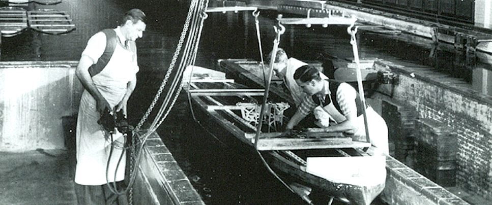
NATIONAL PHYSICAL LABORATORY - A picture from the archives, a large model ship is readied for launch in their test tank. The NPL opened its first ship tank on 5 July 1911. It was 150 m by 9 m wide and held 5000 tonnes of water with a centre depth of 3.75 m. A marine engineer and shipbuilder, Alfred Yarrow, provided £20,000 for the tank's construction to enable the testing of ship models.
It was originally known as 'The National Experimental Tank'; later the 'William Froude National Tank' after the engineer and naval architect; and finally 'No 1 Tank'. The work of the Ship Division was broadly divided into two: investigations commissioned by shipbuilders, ship owners and other external organisations; and the Division's own programme of research. The tanks included apparatus for producing 1 m high waves so that models could be tested in rough or shallow water.
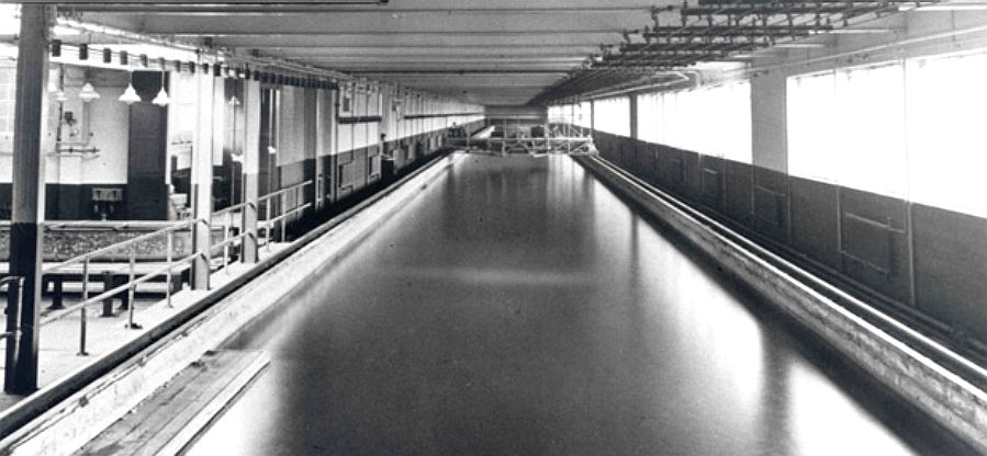
As a result of increasing demands from industry, the Government provided funds for the construction of a second tank, which was completed in 1932. The record number of models tested at the NPL in any one year was 190 in 1944.
The ship tanks were made famous by the 1950s 'Dambusters' film , which immortalised the role of NPL in the development of Barnes Wallis' bouncing bomb: NPL's No 2 Ship Tank had been used to test the bomb that the RAF launched at the dams of the Ruhr in Germany in 1943.
During the 2nd World War, 617 Squadron used special bouncing bombs designed by Barnes Wallace to destroy two dams in Germany. Everyone knows that German engineering is excellent. Barnes knew this, so when calculating the amount of explosive needed to rupture the concrete dams in the Ruhr industrial region: the Möhne, Eder and Sorpe, he added a bit extra - and needed it. Ours is a peace mission, but the basic physics is the same.
On the evening of 16 May 1943, 19 specially-adapted RAF Avro Lancaster bombers of the newly formed 617 Squadron (later called the 'Dambusters'), set out from RAF Scampton in Lincolnshire to attack the dams of the industrial Ruhr in Germany, using the so-called 'bouncing bomb' developed by Barnes Wallis (1887-1979).
ATMOSPHERES
Pressure at depth is typically measured in atmospheres. At the surface of water (sea level), we are at one atmosphere. The pressure on our bodies at sea level is 14.7 lbs per square inch, or 1.03kg per square centimeter in cross-section, about 10.1 N. You'd never know it.
Every diver knows that when they descend to a depth of 10.3m (33.8ft) underwater, they will experience pressure on thier body of two atmospheres (1 atm of air plus 1 atm of water) so 29.4 pounds per square inch (2.06 kg per sq/cm). Fortunately, water is virtually incompressible - and the body is mostly water. For this reason we can dive down to about 100 feet using air, though not for long and our bodies can take that pressure. The gas we breath at this depth has to be compressed to equal the pressure of the depth we are breathing at, otherwise your lungs would collapse from water pressure. Gases like air, CO2, oxygen and nitrogen are compressible. Diving can be a dangerous business if you are not trained and qualified. If you like messing about in water, join a club and do a training course for your own safety.
IT'S NOT WHAT YOU'VE GOT - Most Nissan Micra's only see action for the weekly supermarket run, or to see the doctor. Ours gets us to events and back all over the country, collects sand and cement and timber and is used for scouting locations. She is so useful and economical, we could not do without her. The roof rack turned this mild mannered Clark Kent of a buggy into a handyman's delight. Our Jeep Cherokee will come on line for transporting heavy goods, also useful to cope with our beachfront launch site - when we get to that stage.
TREATED TIMBERS - The treated timbers for the sluice gate are seen above unloaded from our super mini. Yes, it carried all of the 4"x2" timbers seen above in one load and still handled adequately. Our local supplier STAMCO, always gives us their keenest prices for such projects. The service is fast and friendly and the wood is superb quality: 8 Courtlands Road, Eastbourne, East Sussex BN228TR. Building Supplies: 01323 423800 Inspired Home Interiors: 01323 458165. Email: eastbourne@stamco.co.uk
REVISIONS - Although worked out in AutoCad beforehand, you will find that on site, things are never quite as simple. Adjustments needed to be made to cater for brickwork that was not as true as we'd have liked. A site survey told us a lot, but you only really discover the niggles when doing. A nice little touch is including a glass viewing window in the sluice gate after we found a handy piece of toughened glass in the clear up. We'll save that little job until later.
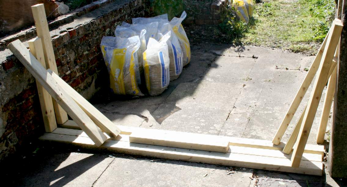
SLUICE GATE FRAME - Okay, here you can see the guide timbers for the frame of the sluice gate. These are to be bonded and bolted to a plywood liner - and the liner is to be cemented in place, also being bolted to the walls and floor, once the cement has cured. Sharp sand is used with waterproofing admixture for a really watertight installation. We will be using a pneumatic rubber seal to prevent leakage when slotted in place. Inflate to seal, deflate to open the gate. Simples.
SLUICE GATES
A gate that we can lift, that is also see-through, might be an advantage. To fill our testing tank the sluice gates are slotted in place. The tank is then filled with water from an onsite water supply. To empty the tank, we will lift the right had sluice gate a small amount, when the water will empty on the other side into a storm drain. We do not need particularly deep water for our tests, reducing the water used, some of which comes from a rainwater collection system nearby.
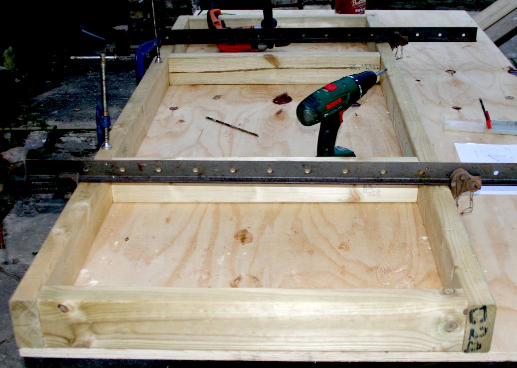
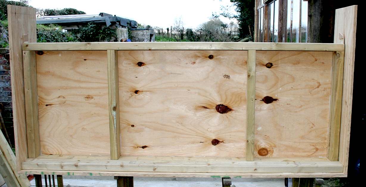
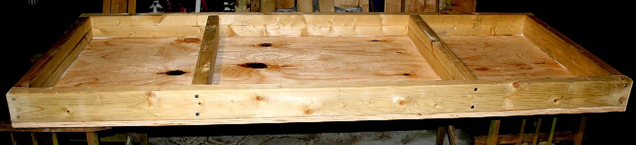
SLUICE GATE - Here you can see our sluice gate under construction. We've used treated 4" x 2" timbers to make a sturdy frame that is held together with 6" steel pins. This frame will be point loaded to simulate a force of 1.4 tons across the frame. The component timbers are locked into place when driving the pins home, to keep it square. April 14 2016.
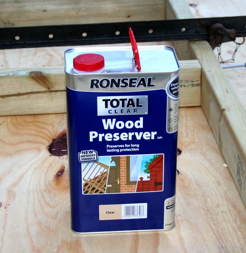
PRESERVATIVE - Where the frame timbers are ready treated, the plywood needs several coats of wood preserver. Our old friends at Stamco in Eastbourne came to the rescue with Ronseal Total at a sensible price. This fluid helps prevent wet and dry rot and woodworm attack.
Our sluice gates are constructed of a treated wooden frame with a sheet of structural plywood as the barrier. We are looking at incorporating a glass portal in one of the gates, but not just yet. The plywood will be treated, sealed and painted to protect the wood, but also so that we can film the models underwater with good visibility.
A sluice gate is traditionally a wood or metal barrier (flat slab) sliding in grooves that are set in the sides of a waterway. Sluice gates commonly control water levels and flow rates in rivers and canals. "Sluice gate" refers to a movable gate that when raised, allows water to flow under it. Usually, a mechanism drives the sluice up or down. This may be a simple, hand-operated, chain pulled/lowered, worm drive or rack-and-pinion drive, or it may be electrically or hydraulically powered.
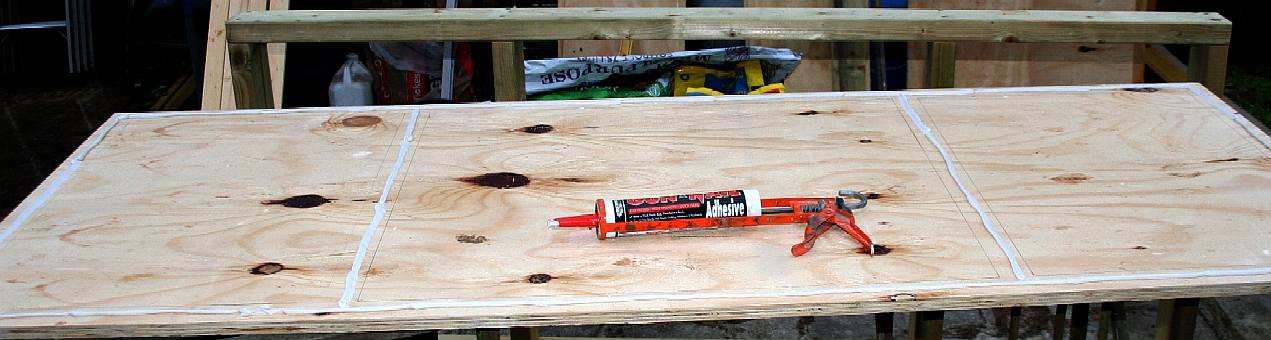
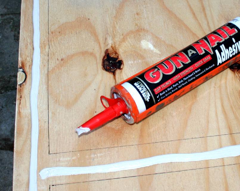
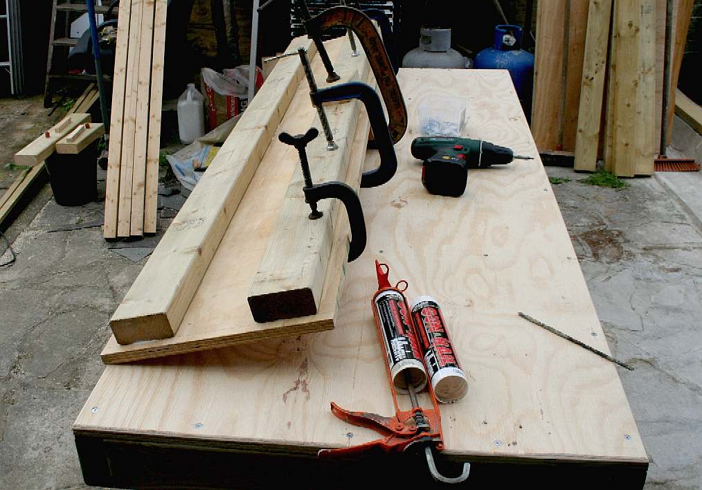
ADHESIVE - This is not just a bond, but also a sealer. The objective is to prevent water seepage between the plywood barrier and the supporting timber frame. In reality, once the plywood is rot treated, the corners will be filled with a waterproof seam sealant. Then, the whole unit will be sealed, primed and painted with a top quality finish in white.
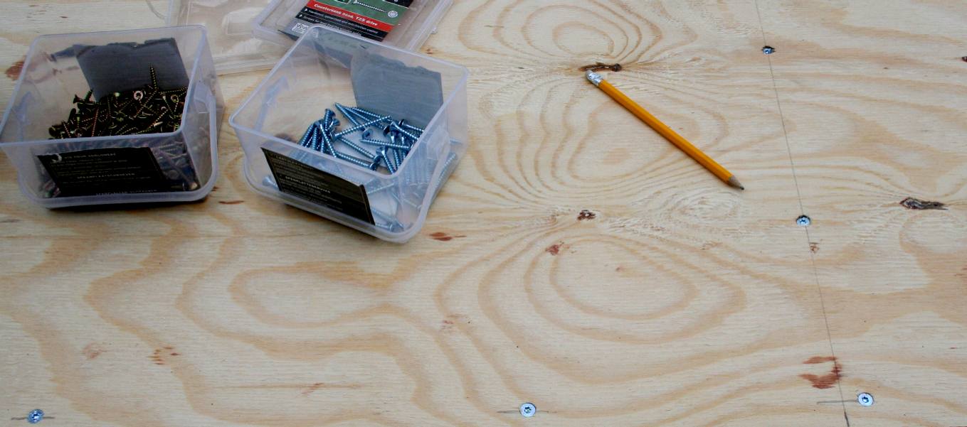
SEALER - We applied a generous bead of high grab adhesive to be sure that when clamped, the adhesive would form a watertight gasket. The plywood is pre-drilled so that the securing screws pull the frame and sheet together. This ensured that when assembling, any timbers that are warped, are straightened as much as possible.
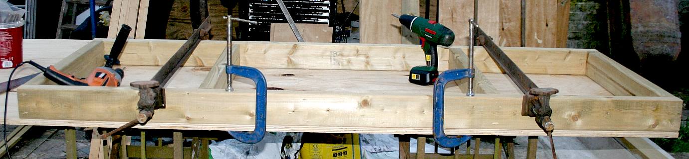
CLAMPING - Once bonded and screwed in place, the whole assembly is clamped again until the adhesive is cured.
FIXINGS - Strictly speaking, screw fixing is not necessary, because the gate is subject to pressure from water that pushes the frame and plywood together. These fixings will though add slightly to the strength of the timbers in bend.
LINER - A plywood liner carries two softwood guides that are bonded and screwed together to make a frame for the sluice gate. Later, 13mm studs will hold the frames to the walls and floor, but for now we need structural integrity independent of the tank it will be fitted into - otherwise we could not manhandle the unit while working on it. Copyright © April 16 2016, all rights reserved. You will need permission from Bluebird Marine Systems Ltd to reproduce this photograph.
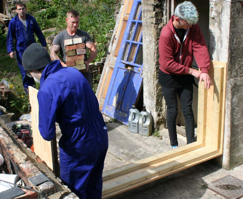
FRAME - The sluice gate is slotted into the lower guides and the side linings are secured in place with wooden shims that are especially cut to simulate the design clearance gap. We have allowed 5mm on either side, because wood expands a good deal, even if sealed to the eyeballs. The gate then becomes the jig for the frame, as the frame is assembled around the gate that will hold in the 13 tons of water that we need to conduct our tests. to ensure a watertight seal, we are using a special rubber seal that we can pressurize to lock the gate in the frame. Copyright © April 16 2016, all rights reserved. You will need permission from Bluebird Marine Systems Ltd to reproduce this photograph.
TREATMENT - The gate and frame can now be treated with a first coat of preservative.
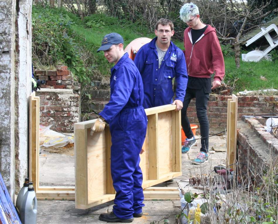
PERFECT FIT - Ross (left) and Jamie (right) slide the frame for the sluice gate into place. Copyright © April 17 2016, all rights reserved. You will need permission from Bluebird Marine Systems Ltd to reproduce this photograph.
GATE - Richard and Chris get ready to slide the gate into the sluice frame to be sure the clearance tolerances are adequate, while Jamie sets up the cement mixer kindly loaned to us by his family. Copyright © April 17 2016, all rights reserved. You will need permission from Bluebird Marine Systems Ltd to reproduce this photograph.
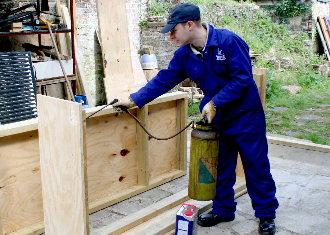
MORE PRESERVATIVE - Ronseal suggest 2 coats of preservative for normal protection, and 3 coats for a bit extra. We are using a 40 year old pressure sprayer for application. During one pump up, the hose split, spraying a crew member liberally before the canister could be de-pressurized. At least the woodworm will leave him alone until bath-time. Copyright © April 17 2016, all rights reserved. You will need permission from Bluebird Marine Systems Ltd to reproduce this photograph.
FURNITURE - By the second coat, the sluice gate parts are beginning to look more like a kitchen cupboard than an engineering item. One more to go and then it's painting tanking time. The underside and backs of the uprights need to be coated with a bitumen based paint to provide a damp proof barrier between the plywood and the bricks and stone floor. When the tank is drained between use, rising damp would be the long-term enemy. Copyright © April 17 2016, all rights reserved. You will need permission from Bluebird Marine Systems Ltd to reproduce this photograph.
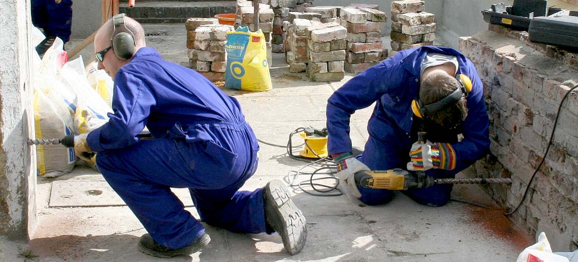
DRILLING - Heavy duty SDS drills are used to sink a 25mm hole in the wall and floor. It was a warm day, making the task more demanding for Richard and Chris. In the background you can see the reclaimed bricks that are being recycled after cleaning. Copyright © May 1 2016, all rights reserved. You will need permission from Bluebird Marine Systems Ltd to reproduce this photograph.
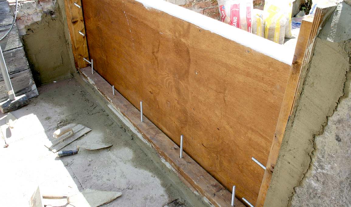
CEMENT - The sluice gate is cemented in place with all 22 studs located (not fixed) in the wall and floor drilled holes. These will be removed, the holes filled with a strong cement mix, and then reinserted for the cement to cure for a few days - before tightening the securing bolts. Copyright © May 1 2016, all rights reserved. You will need permission from Bluebird Marine Systems Ltd to reproduce this photograph.
BOLTS & SEALS - Here you can see the rubber seal that is a snug fit and can be inflated if necessary to lock in place. Copyright © May 1 2016, all rights reserved. You will need permission from Bluebird Marine Systems Ltd to reproduce these photographs.
MORE FIXINGS - Where we experienced a stud failure, we decided to use more fixings for the sluice frame. Copyright © May 9 2016, all rights reserved. You will need permission from Bluebird Marine Systems Ltd to reproduce these photographs.
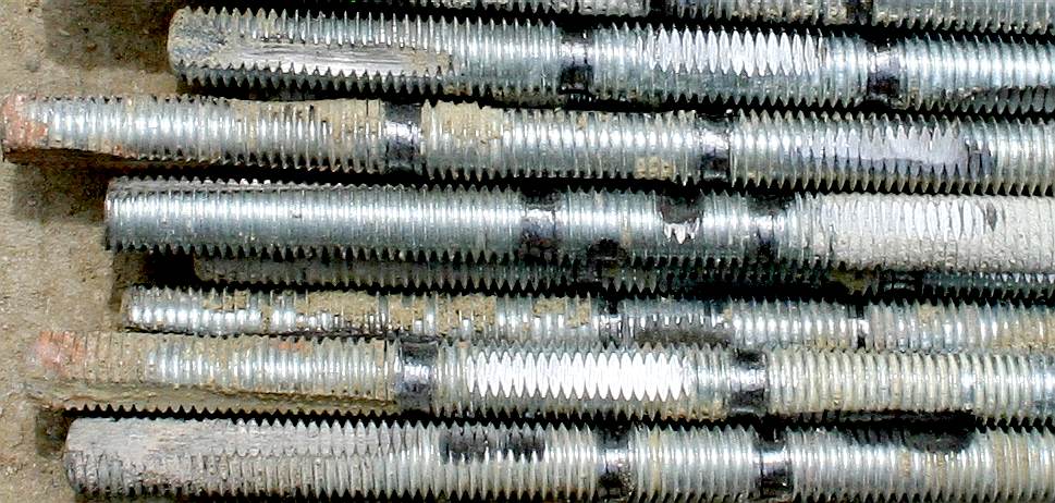
STUDS - The steel studs were reground with additional flat sections, grooved rings, and were roughed with wire brushes to increase adhesion of the cement. The idea is that the flat sections stop the rods spinning, and the ring-grooves stop the rods from being pulled out of the wall when the nuts are tightened. Copyright © May 9 2016, all rights reserved. You will need permission from Bluebird Marine Systems Ltd to reproduce these photographs.
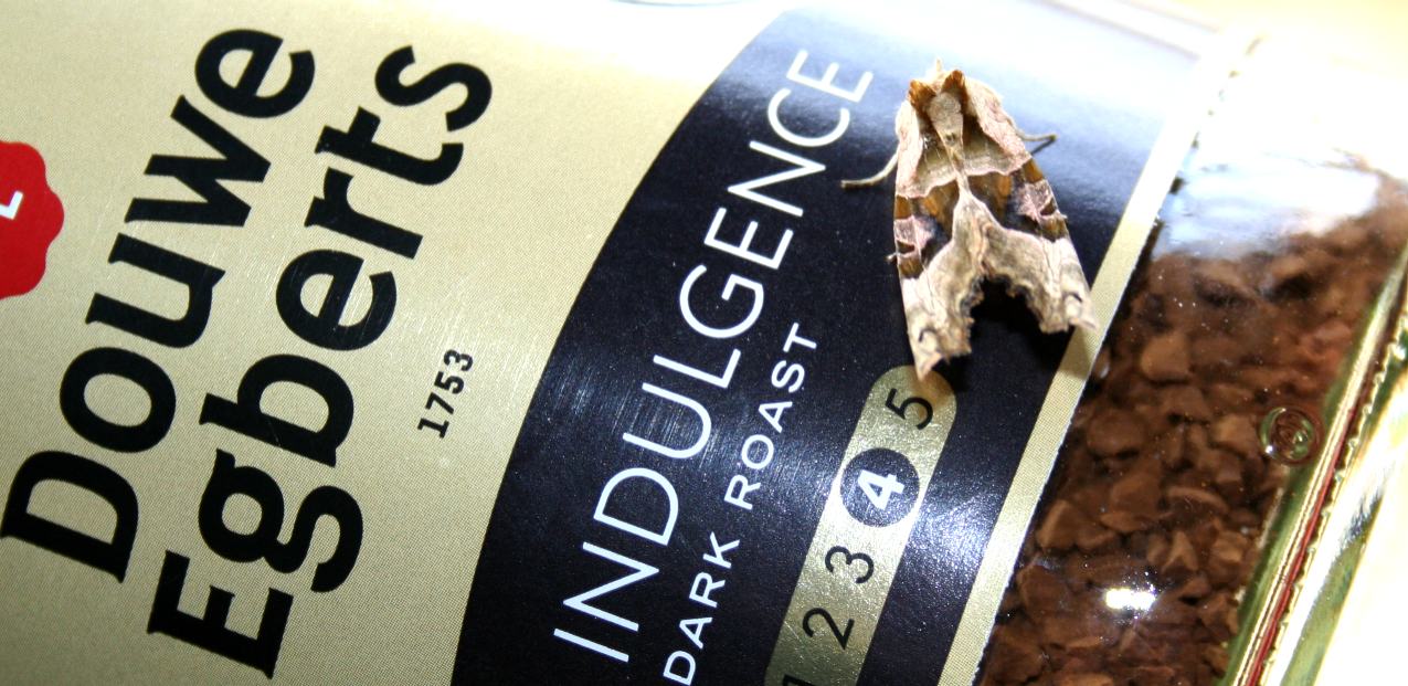
COFFEE TIME - Back in the canteen, and fortunately for our winged friend, we found that a moth had alighted on a jar of coffee, matching the colour scheme of this famous (and delicious) brand of one of our favourite tipples. (We are also fond of Earl Grey and Assam tea) Another incredible thing, is that the moth was more than happy to sit tight while we made several rounds of drinks during the course of an afternoon - in the process lifting up, opening and putting this jar down again many times; a bit more carefully than normal. That was the level of attraction that this beautiful animal had with the Douwe Egberts beverage. It simply would not let go - and we loved it for that tenacity. What would Charles Darwin have made of it? Observation is what science is all about. Copyright © May 10 2016, all rights reserved. You will need permission from Bluebird Marine Systems Ltd to reproduce this photograph.
BRICKWORKS - There are still a few niggling adjustments to be made to the pre-existing brick features, before the last sections of render can be applied. In this picture you can see that the steps that went nowhere, have now been cropped back. The flora is beginning to sprout as an accelerated rate because of the heat of the last few days. Copyright © May 9 2016, all rights reserved. You will need permission from Bluebird Marine Systems Ltd to reproduce these photographs.
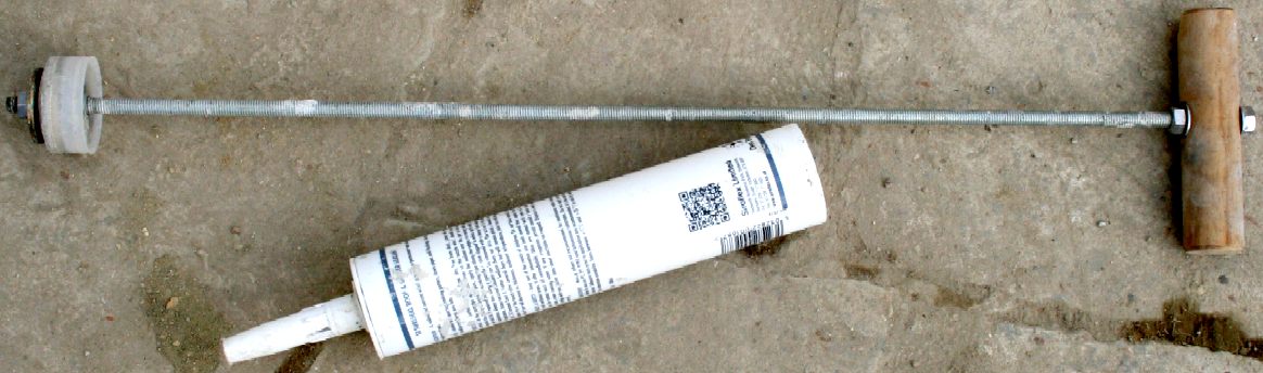
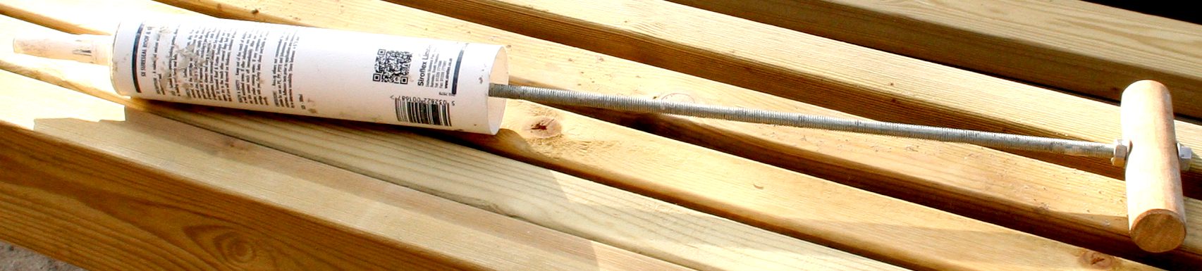
CEMENT PUMP - Okay, so having drilled 22 holes some 200-250mm deep, how do you get the cement right to the back of the hole? Well, all of our local builders merchants and DIY stores had nothing suitable - for example, a cement pointing gun - leaving us somewhat in the lurch. Though Stamco and B&Q both stock pointing guns that unfortunately, don't have the depth. Then Chris had a brainwave, why not convert an empty sealant tube. He gave the task to our in-house fabricator, who came up with this solution in less than 20 minutes - and fortunately - it worked. Copyright © May 15 2016, all rights reserved. You will need permission from Bluebird Marine Systems Ltd to reproduce these photographs.
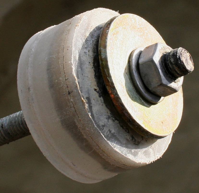
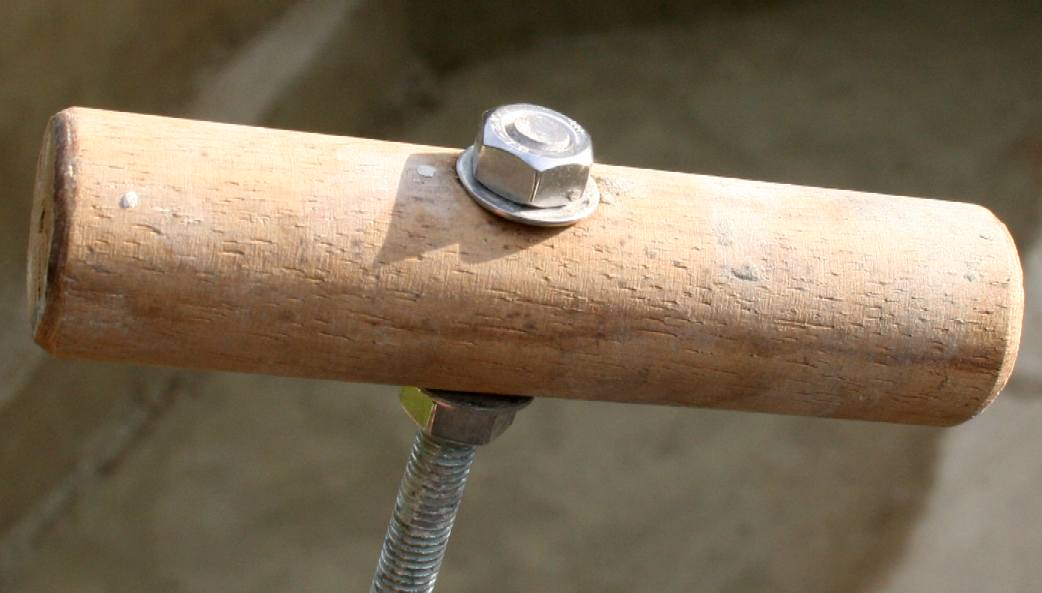
PISTON & HANDLE - You've probably not taken an empty sealant tube apart before (we hadn't), but if you do you will find quite a nice nylon piston inside. Take a couple of large washers and clamp the piston to a threaded rod between a couple of nuts. You will then find that the compressed piston no longer fits inside the plastic sealant tube, but using an angle grinder with a sanding disc, you can grind off the leading edge so that it does fit again. Be careful to rotate the piston smoothly, or you will create flat spots - and of course the assembly will then be useless. Next, find some dowel and drill a hole for the other end of the threaded rod. Our rod is a bit too long, but we were on the clock, with the cement already mixed (rather stupidly) before our pump was made or tested - so no time to take apart and re-assemble. Having drilled a hole, cut the dowel to length and bolt up tight using a couple of washers. Chamfer the ends for comfort and insert into the empty tube. Copyright © May 15 2016, all rights reserved. You will need permission from Bluebird Marine Systems Ltd to reproduce these photographs.
CEMENT PUMP - This is it. It's a bit like one of the old brass stirrup pumps for spraying insecticide, and it has a good range when firing clean water. We found it did not suck up the cement (like a stirrup pump sucks up water), meaning you have to pull out the piston and load with cement from the back. As each hole took almost a whole tube of cement, it was fairly time consuming inserting 20 studs, especially as each stud had to be primed with cement to be sure of a solid bond. Copyright © May 15 2016, all rights reserved. You will need permission from Bluebird Marine Systems Ltd to reproduce these photographs.
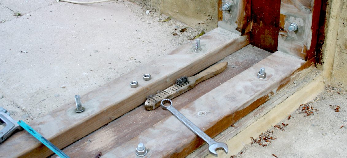
NUTS & BOLTS - Finally, with all 22 studs cemented in place, they are cut down to a sensible height and the stainless steel nuts are tightened down. Before that, cement has to be removed from the threads with a wire brush. A HSS hacksaw blade makes light work of the studs, provided the blade is sharp. Leave for a couple of days before doing anything like this, and another week before final tightening. Cement takes a while to reach full strength. Many hundreds of year in fact. But in practical terms, 7 - 14 days should cure the cement sufficiently to take the strain of a stud like this. Copyright © May 14 2016, all rights reserved. You will need permission from Bluebird Marine Systems Ltd to reproduce these photographs.
RENDERED - What a beautiful day it turned out to be. The apple tree on the left is blossoming, and best of all we completed the rendering of all the walls that need to be waterproof. We even started on the wooden top frame that will carry the gantry support beams - and we borrowed a MIG welder that can cope with the small spools of stainless steel welding wire sold at our local Toolstation in Eastbourne. This end of the test tank will have a hatch (short doors) to keep leaves and birds out. We also have three cats that patrol this area for mice - and we don't want either felines or rodents taking an unauthorised dip (stowaways) while we are not looking. Copyright © May 15 2016, all rights reserved. You will need permission from Bluebird Marine Systems Ltd to reproduce these photographs.
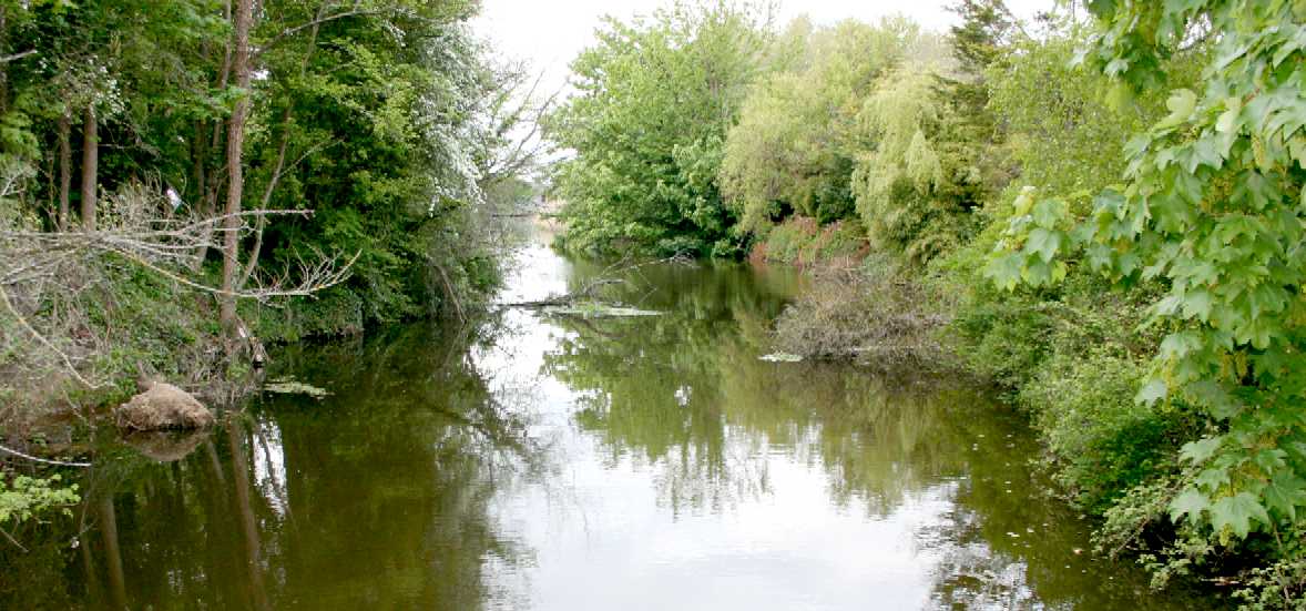
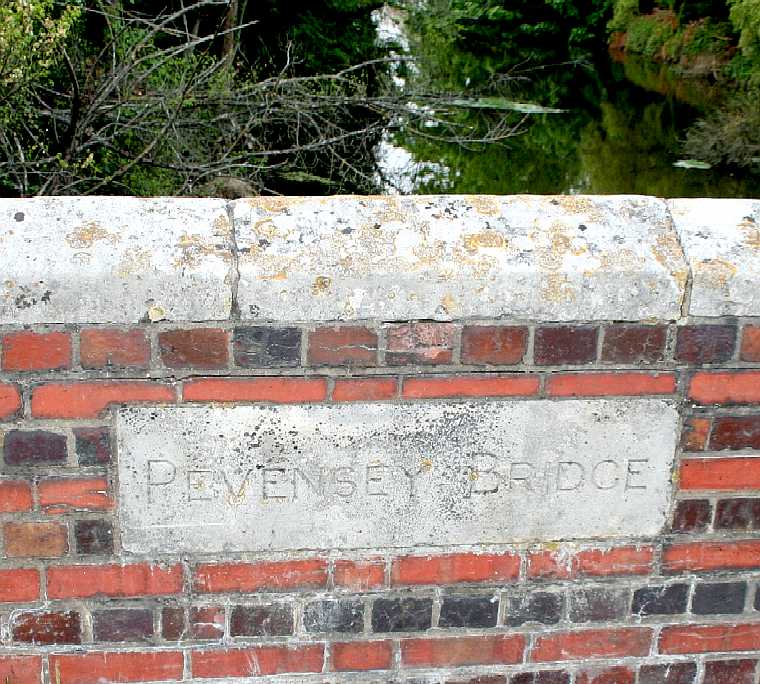
PEVENSEY HAVEN - This is the river that the sluice gates below control. The river (Pevensey Haven) is popular with anglers. Copyright © May 17 2016, all rights reserved. You will need permission from Bluebird Marine Systems Ltd to reproduce this photograph unless for private or academic study.
SLUICE
GATES
- TQ 6404 38/272 30.8.66 Pevensey Bridge was widened on the north side by East Sussex County Council
in 1933. But some of the old stonework dating from 1675 was re-used to face the 2 cutwaters and the flanking portions, the eastern flank having
that date on it. The south side dates from 1816. This is of red brick and grey headers in alternate courses and consists of one wide and 2 narrow
round-headed arches with the date 1816 on the stone keystone of the wide arch, with ashlar side portions, as on the north side.
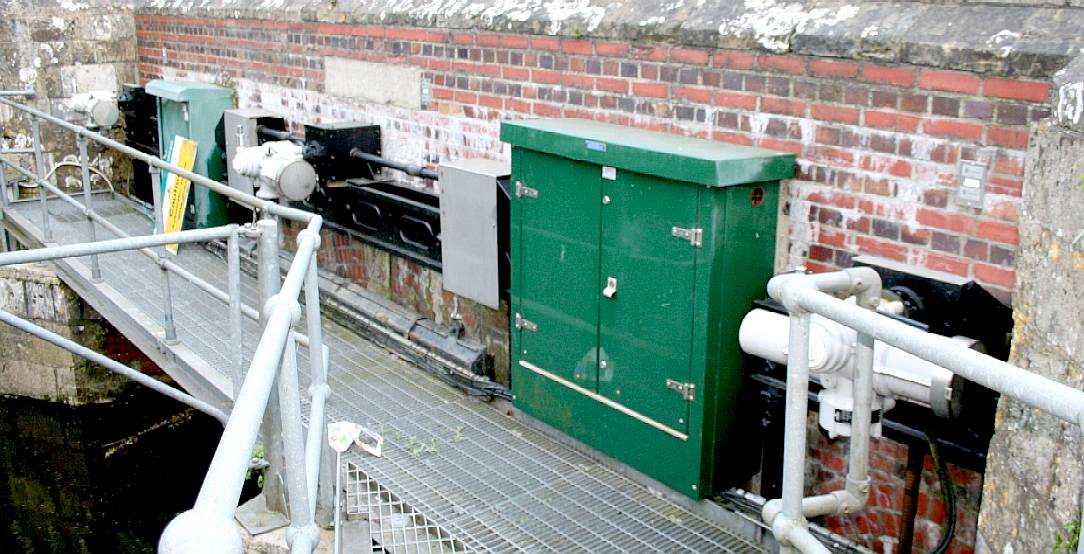
GRADE II LISTED BUILDING - In the picture on the left we can see the cast iron frame of the sluice gate. The original manual wheel has been replaced with reduction gearbox mated to an electric motor that may be remotely controlled. Copyright © May 17 2016, all rights reserved. You will need permission from Bluebird Marine Systems Ltd to reproduce these photographs.
LINKS & REFERENCE
https://avaaz.org/ https://www.uni-due.de/IST/ismt_circulation_tank.shtml http://www.edesign.co.uk/portfolio/plymouth/ https://www.plymouth.ac.uk/research/institutes/marine-institute/coast-laboratory http://www.building.co.uk/making-waves-plymouth-marine-laboratory/5069697.article info@marin.nl http://www.britishlistedbuildings.co.uk/en-295508-pevensey-bridge-pevensey-east-sussex http://www.marin.nl/ https://en.wikipedia.org/wiki/Maritime_Research_Institute_Netherlands http://www.designindaba.com/articles/creative-work/award-winning-ocean-cleanup-team-launch-their-first-open-water-test http://www.bbc.co.uk/news/uk-england-35909651 http://www.toolstation.com/ http://stamco.co.uk/
BRICKS & MORTAR - CARRIAGE - DRAINAGE - FACILITIES - FILTRATION - GLASS & PAINT - GANTRY - GIMBALS - HATCHES - HYDRODYNAMICS HISTORY - INSTRUMENTS - LABORATORY - LAMINATING - LOGISTICS - OUR TEST TANK - PROOFING - REVIEWS - SCREEDING - SEAVAX TEST VIDEOS - SLUICE GATE - SOLAR BATTERIES - WAVE MAKING - WIND MACHINE
|
||
|
This page is Copyright © 2018 Bluebird Marine Systems Ltd. The names Bluebird™, Bluefish™, Miss Ocean™, RiverVax™, SeaNet, SeaVax™, and the blue bird & fish in flight logos are trademarks. All other trademarks are hereby acknowledged.
|