|
|
BLUEFISH - AUTONOMOUS DEVELOPMENT PROGRAMME
|
|
||
|
MAKING THE JIG & JIG TOWERS IN WOOD
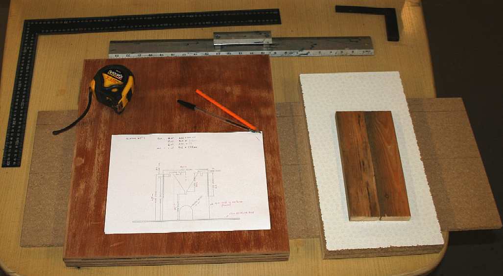
To speed up production, we produced CAD drawings and cutting lists, with all of the dimensions included and the number of items in different materials in a check-list. This way the carpenter does not have to think about allowing for the thickness of ends, bases, etc, and can concentrate on accurate sawing.
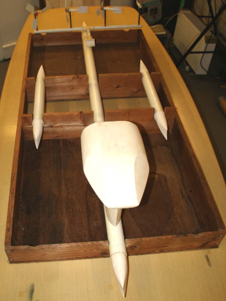
EARLIER SWASH JIG - FIXED DESIGN
As with all development, we learned from the older Jig. The original (SWASH) Jig has two central holders for the outrigger hulls screwed to the main frame sides. As you can see the hull sections sit neatly in their slots about midway, but they cannot be adjusted fore and aft for interference wake tests as per a Type I configuration (see Leo Lazauskas). We can though throw away the rule book according to Mr Lazuakas, where the increase in harvested energy for a stable hull, more than makes up for any drag increase - and that is where our active outriggers really come into play, to be in a position to trim the running resistance to the minimum.
The new Jig is therefore adjustable, with a central box unit to carry the swing-outriggers. The box unit may be slid forward and aft, to accommodate testing of the outriggers in different positions (as in assembling further aft, etc). The old static Jig is shown below with the old hulls in ordinary plumbers acrylic pipe - it is cheap, but it is heavier pro-rata, less stable and near impossible to work into bespoke shapes, such as foils, fins, etc.
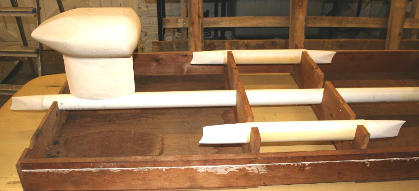
Old Jig 2011: The above is the original timber jig, for a smaller hull diameter and narrower beam. The side shot reveals that the helm (pod) design has also changed to a simpler triangle for the new Bluefish (SNAV) platform; a triangle being the most efficient engineering design. Weight is an important consideration with a solar powered ship. This jig relied on a flat table or other surface to prevent flex.
You can easily see the modifications in the new SWASH hull over the earlier prototype in the photograph below by comparing the Jig ends side by side. Four hull holders are required for each jig. It is best to clamp the patterns together for cutting as one - to eliminate error as much as possible.
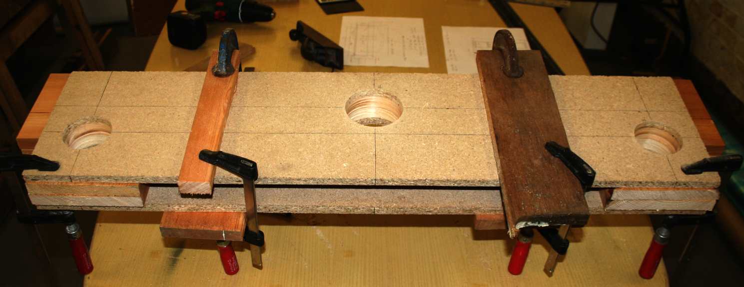
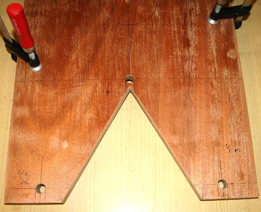
New Jig 2013: Four parts of the Jig must have identical rounds in which to sit the hull tubes. The answer to this is to mark out all four timbers and then clamp them for holes to be bored.
The four templates are shown above clamped together so that boring may take place from each side in turn. The holes should line up perfectly in the middle if you've done it right.
Old Jig 2011 v New Jig 2013: You can see the difference in outer hull spacing, and that the diameter of the hulls has increased. The new Jig is adjustable to be able to take 60-75 mm tubing. This is because we are going to test various hull configurations. A larger hull diameter is preferable for the ROV equipped hydrographic/surveillance versions of the Bluefish ( SNAV) platform.
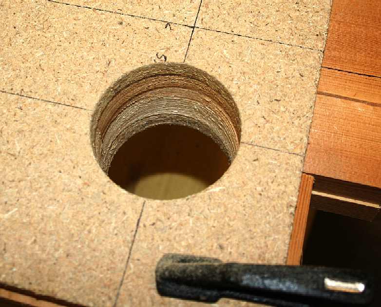
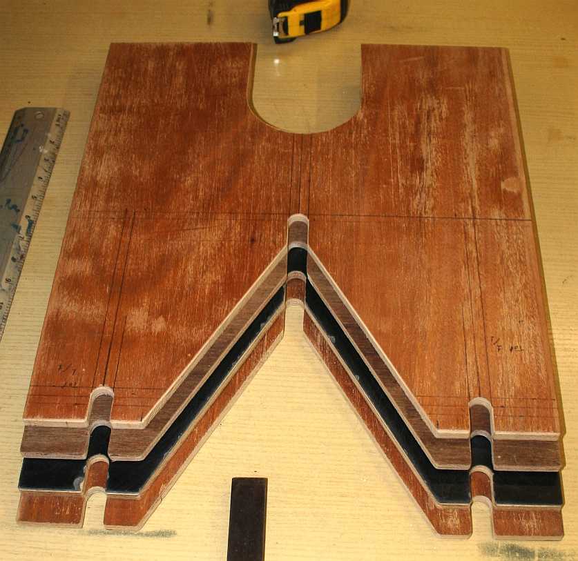
You can see from the picture below that the holes from either end line up in the middle. Should this not be 100% accurate, you may still be able to finish off with production paper and a keen eye, to take out minor discrepancy. A liner is required in any event, which also allows shimming.
Close up of the hole bored, showing the four components - now all matching. Accuracy of marking out is essential. A sharp pencil is good, but we use a fine black ball point pen, or fine tipped felt pen when marking aluminium. Then, decide which side of the line you are cutting, or straight down the middle. When beginning a cut, use your left thumb like a Vernier gauge, to precisely control the saw path. The first few draws are the most important.
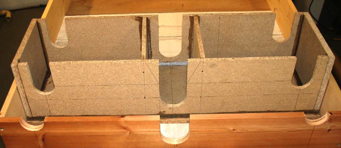
The sliding outrigger carriage, being glued and pinned using ordinary PVA adhesive and steel oval nails. Work quickly to secure the base board to square, before the adhesive sets, otherwise minor lozenging while handling will weaken the joints. Before bashing away with a hammer, the pin positions are pre-drilled while the sides are clamped. Using this method, the box will assemble just as before when clamped. Give or take a smidgen.
Follow the build and testing of this revolutionary SWASH design on these pages. The space-frame superstructure that interconnects the flying accommodation pods is made from 15mm alloy tubing. The submerged hull section (and the trimaran outriggers) are to be made from thin wall 18g aluminum tubing, as are the fore and aft foils of this 2.1m long model (not including wind gens. The specially shaped cones are to be molded from fiberglass as in previous models. There are six of these.
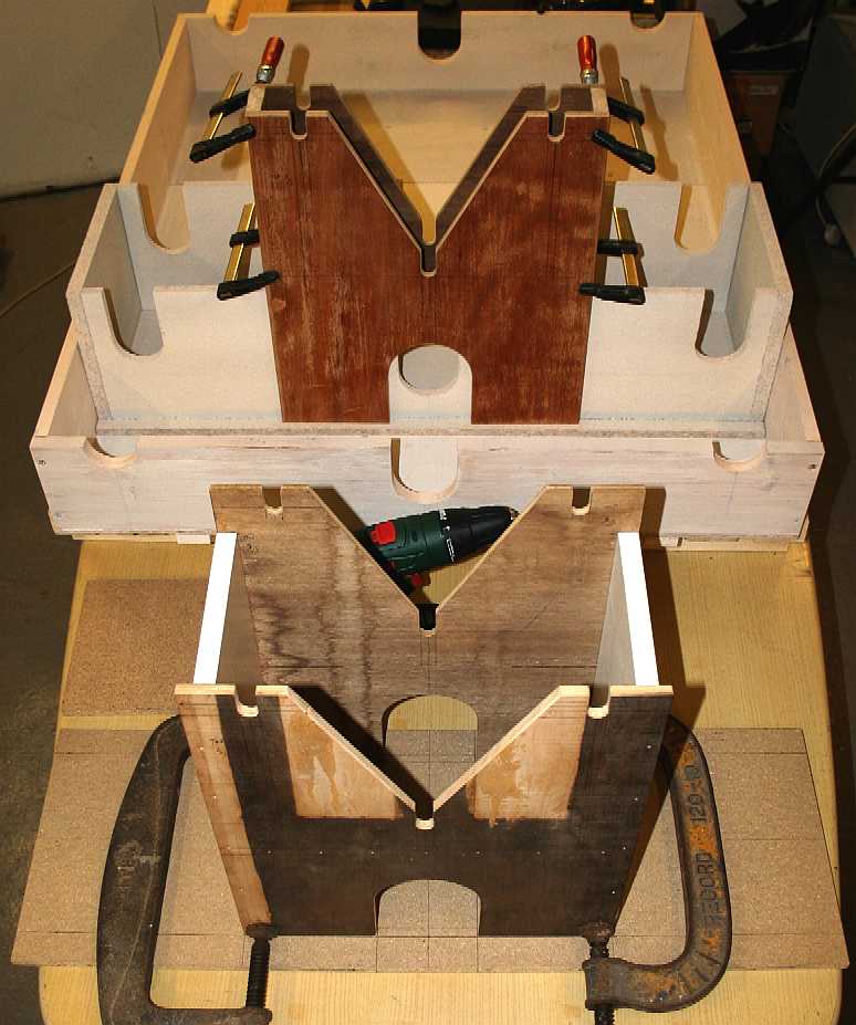
The sliding outrigger carriage assembled with base attached and internal box dividers added to stiffen the structure - seen here inside the main box housing, with good clearance to make sliding adjustments easy. Once positioned, the unit can be locked while working on a hull. More refinements are to come.
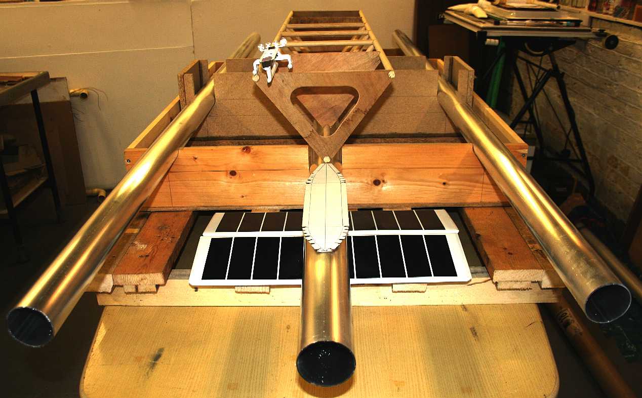
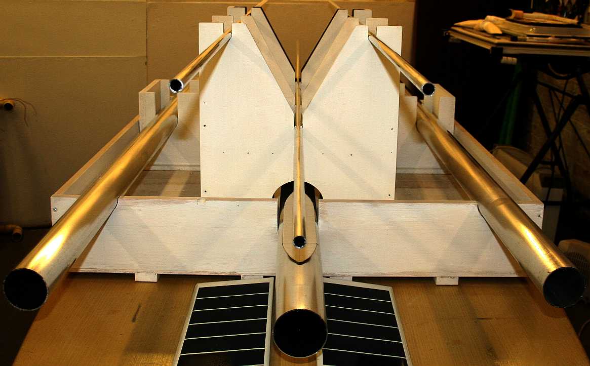
A test fit of the aluminium hull tubes (uncut) and the wooden superstructure (spaceframe) made by hand last year. The superstructure is much higher and will need additional jigs to position it correctly in relation to the hulls. The rigid timber base is causing problems and our trusty Bosch electric plane locked up - so need to service pronto. A 25mm sheet of plywood will be added to the base timber frame once the high spots have been planed down. Then the jig proper will be bolted down. You can see the 1/200th scale SNAV test model (mascot) balancing on the top left of the dowel frame test piece. There is more of the jig to come - the parts that hold the spaceframe in situ aloft while the joining leg-fins are attached to the hulls.
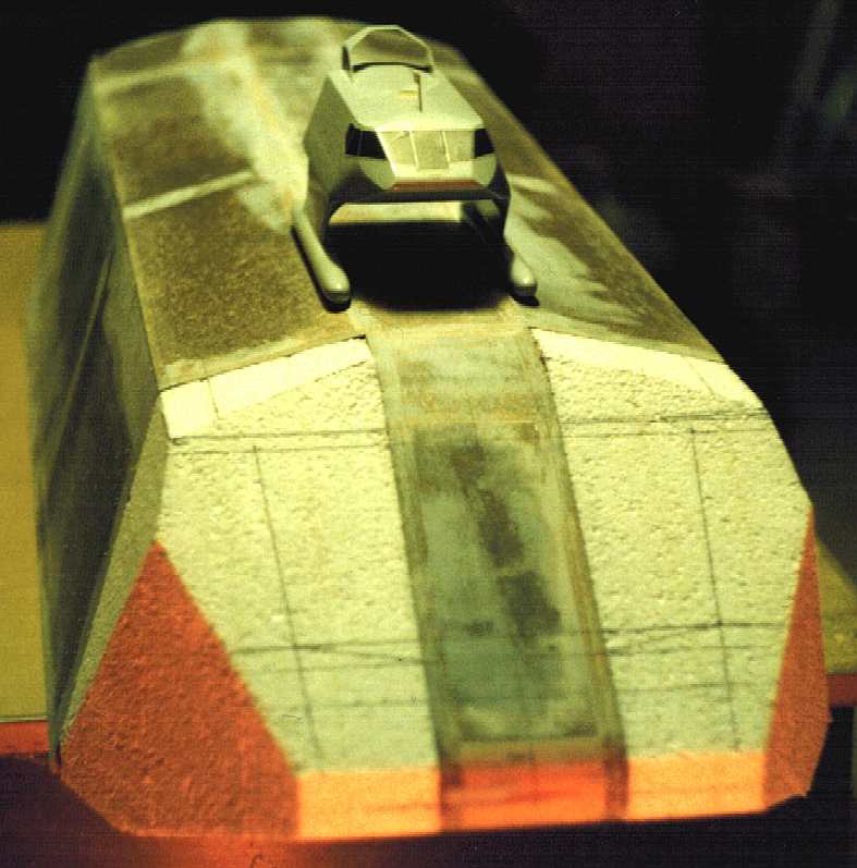
Funny how history repeats itself. The above is the original SNAV MkI solar powered SWATH model hull under construction (actually master for mould making) with its 1/100th scale 'mascot' perched on its back. This was from 1993/4. As with the 'Bluefish' the baby model was used for all manner of flotation and stability tests, but could not be piloted to reveal the hull handling characteristics. That would need the 1/10th radio controlled model and trim tanks.
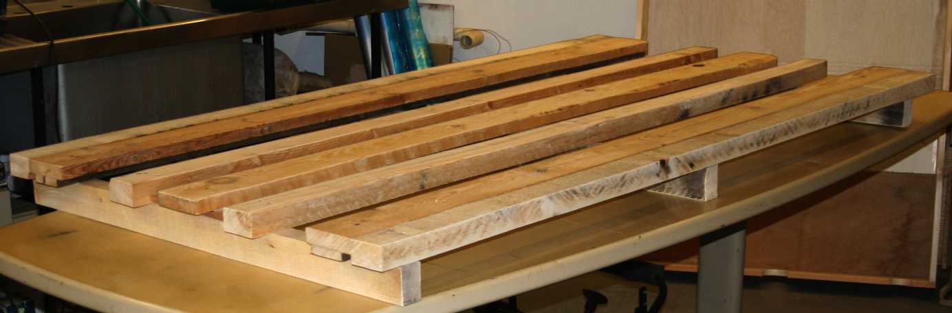
Where the original jig relied on a flat surface, on the MkII we have constructed a solid base of sturdy timbers onto which to mount the (fine) box-jig. The plane was repaired and used to remove high spots before a sheet of 25mm ply is screwed on. The base has also been sanded to take off splinters. With fold down legs attached and heavy-duty locking braces this base will make a useful cutting table for some of the parts of the full size vessel. The jig for the 43 meter ship will not be made like this.
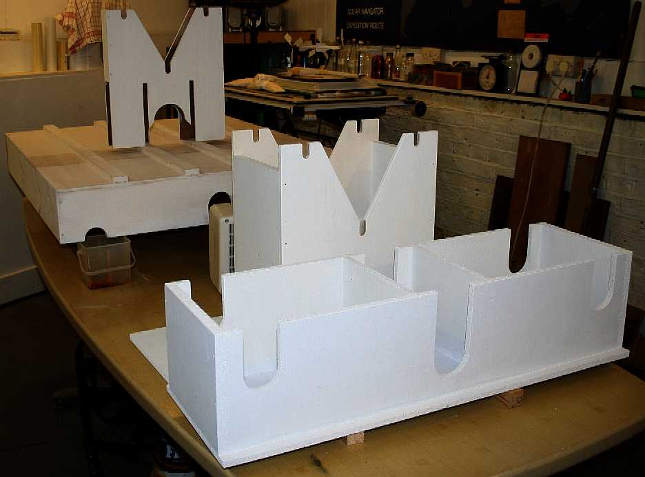
As with the main Jig, the Jig Towers (towers that sit in the Jig to place the superstructure with precision above the ship's hulls) were the subject of CAD drawings and a cutting list. Shown above are the blanks for the two towers. They needed to be cut with the same accuracy as the four hull mounting guides.
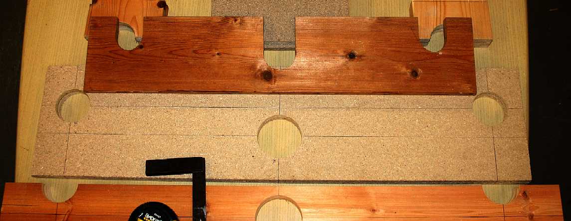
For the two towers, we need four of these templates with the base and saddles for the alloy tubes arranged precisely. The three holes show here are the most critical. A pillar drill was used very slowly milling out the holes from 1.5mm to 16mm. These templates were too large to fit into a sliding crosspiece. They had to be positioned and locked in place by hand - requiring extreme concentration. A center punch was used just as though working in metal.
All four tower templates, showing the accuracy of the cutting. If these were out of alignment - even by a small amount, the alloy tubes would not fit into the slots and would buckle - rather than run true. The position of each template is numbered and sequenced to make the next assembly stages as idiot proof as possible. Our boat-builder tells us that it is much easier working in metal. Metal is less prone to warping for example.
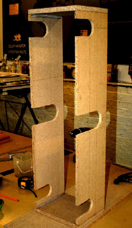
The four upright templates are now assembled using 'G' clamps. Before assembly, the base and other parts are marked out. All of the component parts are pre-drilled and countersunk. The Tower-Jigs will be screwed in position. You are probably thinking that the Jig is starting to look more complicated than the model. That is not so. The model is a miniature of the full size vessel, with many times more aluminium hull parts. That is why a Jig is a good investment. The timber used for the Towers is recycled from odds lying about the shop, so not included in any costings.
How about a nice coat of paint. The wooden sections are sanded, blown clean with an air hose and dusted with a tack-cloth. The Jig parts are sealed, primed and finished in white. White is best in a lab. It helps you to concentrate on the work piece, shows up any misalignment, and when assembling delicate electrical and electronic components, parts are easier to find if you drop anything. The bases of the sliding jig sections are waxed and polished. This will enable them to glide easily on the painted inner box surface. There is nothing worse that a mechanism jamming when you are trying to micro-align. That reminds us, the hulls will need to be checked for correct alignment with lasers.
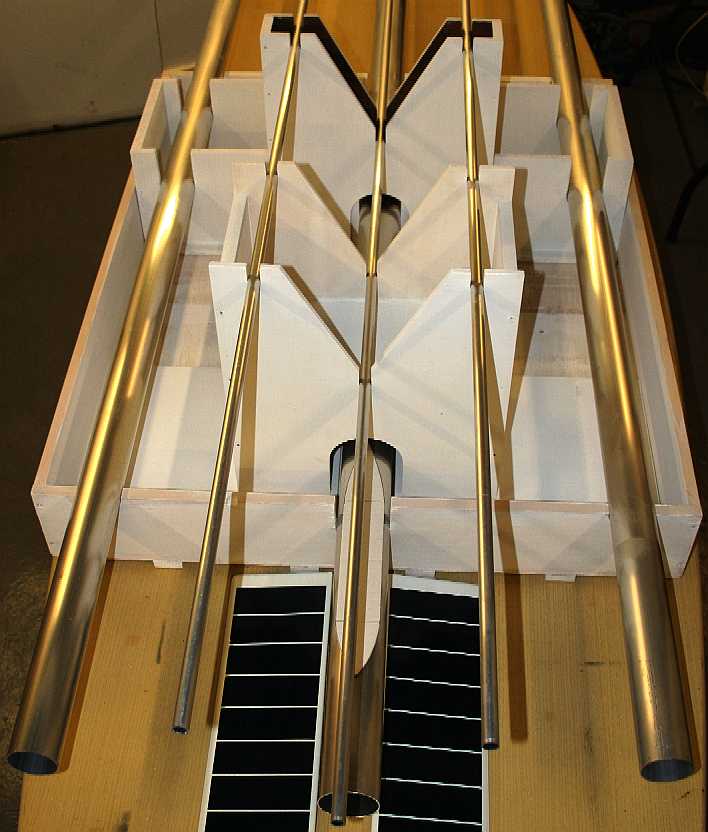
Well, that all seems to fit quite nicely. Phew! Just a few more checks and we can have a nice weekend.
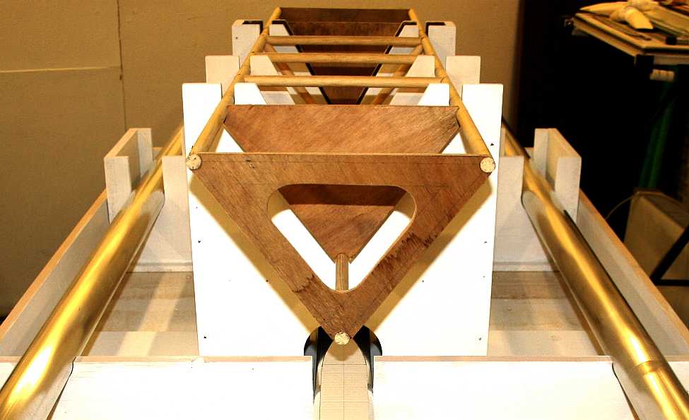
Do you remember the wooden superstructure made almost exactly a year ago (August 2012) without the benefit of a jig? Here it is slotted into the Jig-Towers - and it fits rather well. There is some slight warping at the rear where it has been standing in a damp workshop. Nothing too serious and easy to rectify.
Right. Back in with the alloy tubes - it's time to mark them up and cut them to length...... This picture was taken on the 12th of August 2013.
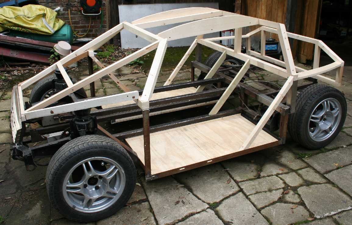
We are taking a breather from project Bluefish ZCC, waiting for our patent application to hopefully proceed to grant, or revision before grant. Meantime we are using our skill in woodworking to produce an electric prototype city sports car seen above - which car features instant cartridge exchange refueling and is also to be the subject of a patent application (possibly to be enhanced) from what we learn during construction and testing. This picture was taken in May of 2014.
BLUEFISH DEVELOPMENT PROJECT INDEX A-Z
TIMBER LINKS
http://www.travisperkins.co.uk/
Solar House, BN27 1RF, United Kingdom + 44 (0) 1323 831727 +44 (0) 7842 607865
EARLY DEVELOPMENT TEST MODELS - LINKS
Blackcurrant 1 | Blackcurrant 2 | Catamaran Hull Design Drag | SWASH | SWATH | Trimaran
|
||||
|
This
page is Copyright © 2014 Bluebird Marine Systems Ltd.
The names Bluebird™, Bluefish™,
SeaNet™, and the
blue bird
& fish in flight
|
||||