|
|
BLUEFISH ZCC - ENERGY HARVESTING DEVELOPMENT PROGRAMME
|
|
||||||||||||||||||||||||||||||||||||||||||||||||||||||||||||||||||||||||||||||||||||||||||||||||||||||||||||||||||||||||||||||||||||||||||||||||||||||||||||||||||||||||||||||||||||||||||||||||||||||||||
|
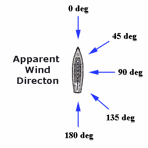
Apparent wind direction is measured in degrees from '0' with a boat heading into the wind. The true wind is the wind you feel when you are not moving. The apparent wind is the wind you feel when the boat is moving, comprised of the true wind and the wind you make as your boat travels along.
GIVE IT A WHIRL
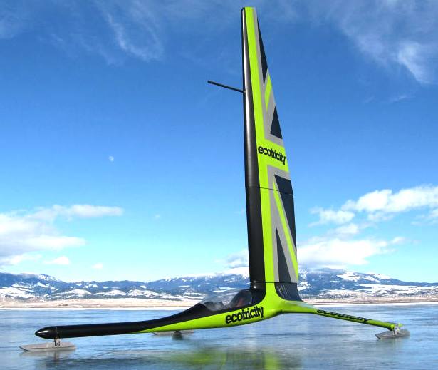
Naval architects are a conservative bunch, not unnaturally, since lives are at stake. But serious innovators cannot afford to be chicken when it comes to trying out ideas - and that rules out the establishment when it comes to the really ground breaking stuff. Several times the stability of the Bluefish design has been questioned. On that basis a tall ship would stand no chance of ever being built - because it is unstable. The proof though is in the pudding - as to workability. The system proposed just has to be tried to prove the pundits or ourselves wrong. But what is wrong, is that not simply another step to getting it right. "Fie sir a man could not draw breath at such speeds" That was a learned doctor's response at the turn of the century to a motor car that could travel faster than 50mph. And that is why you should never let an expert put off experiments that challenge conventional thinking. At the same time such progress will help clean the air, slow climate change, and move the world towards renewable energy independence.
WIND ENERGY
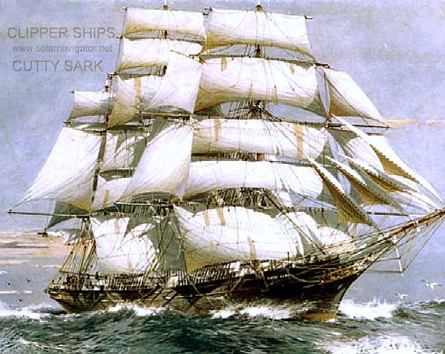
Wind is an abundant renewable source of energy that for transport purposes is woefully under used, mainly because of our love affair with diesel engines. The question is for how much longer should we ignore free energy from nature - when the technology to harvest it is available off the shelf. It was not long ago that all sea trade relied on the "trade winds" with clipper ships like the Cutty Sark plying their passage at respectable speeds approaching 15 knots. Then steam engines came into the frame burning coal. Hoisting and renewing sails was overtaken by the controllability of steam. Steam was in turn ousted by the convenience of diesel, and now diesel is considered dirty and expensive - so we may be about to come full circle, provided that we can convert wind energy and store it, to load level.
Energy harvesting is all about conversion, storage and load leveling. Left: The Cutty Sark in 1870 managed 15 knots on wind power alone and no storage. It is a shame that the speed achieved was not translated to 15 nautical miles in the desired direction because of the need to tack from time to time. When stern-on 15 knots did equal 15 miles traveled per hour and some angles to the wind is a speed multiplier. By using the trade winds, progress was rapid. The direction of the trade winds though, would not give one the shortest route between two points. How might we overcome this problem? We are thinking on it. Right: Great conversion, but no storage - 'Hydroptere' broke the outright sailboat speed world record in 2009 when it sustained a speed of 52.86 knots for 500 metres in 30 knots of wind. Hydroptere can accelerate from 20 to 45 knots in just ten seconds. On the 24th of November, in roughly 25 knots of wind the 'Vestas Sailrocket' ran a 500m course at 65.45 knots (75.32 mph) with a 68.01 knots (78.26 mph) peak. Both records were ratified by the WSSRC for 500m and mile distances.
WIND AS A VECTOR
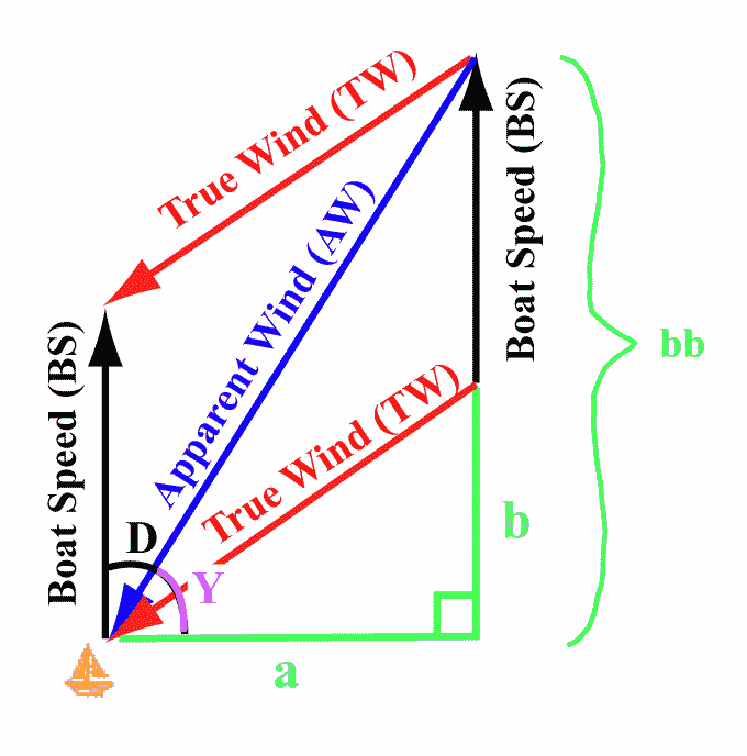
For most ships wind as a vector is a hindrance to forward motion unless stern-on, or as near stern-on (180 degrees) before approaching beam-on (90 degrees). It is described by wind speed and the inverse of wind direction. In a vector diagram such as a wind triangle (above), wind direction is stated as the direction the wind is blowing from.
SAILS - In a sailing ship using conventional sails made of cloth material, the wind energy is used directly to propel the ship at an angle to the wind, typically using a keel as an enhanced pivot.
ROTARY SAILS - In a rotary sailing vessel, a bladed turbine converts wind energy to rotary motion that is used to drive a propeller. That of course means that the progress of a vessel so equipped is entirely dependent on wind blowing at all times, much as any other sailing ship - so lacks a reserve.
SOLAR POWER ALONE
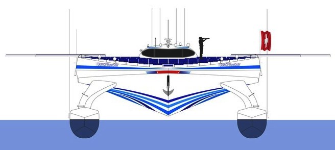
The ship below (Planetsolar) is solar powered. It captures and stores electricity, using some of the captured energy to drive the ship directly. When there is no sunlight to make electricity, this ship runs from its batteries. Planetsolar harvests no wind energy, save that from following currents incidental to its passage.
Head on end elevation of the Planetsolar - solar wings extended and not a sail or rotor in sight. Compare the relatively large frontal area of this boat to that of the Bluefish ZCC below. The Planetsolar weighs 95 tons. It has a power to weight ratio, or more correctly, an energy harvested to displacement ratio of .98kW per ton, from which it manages 3-5 knots continuous cruising speeds, even with a large frontal area - a tremendous achievement. Can you imagine the performance increase if they added wind turbines and reduced their frontal area?
IMPROVING THE POWER TO WEIGHT RATIO
One way to improve the power to weight ratio is to supplement energy from photovoltaic panels with energy that is captured from the wind, by converting that energy to electricity. In this way energy from the wind may be stored. Rotary sailing ships do not need to tack like ships using cloth sails that are beating to windward (sailing directly into the wind). Tacking at 30-45 degrees left and right of wind direction seriously reduces the efficiency of a sailing ship and complexity of vessel operations.
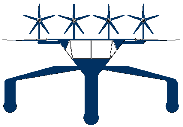
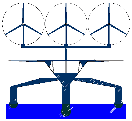
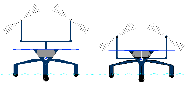
Our basic design below (Bluefish ZCC) also uses photovoltaic panels to capture energy as electricity. The wind turbines seen above the flat solar panels convert wind energy to electricity, which can also be stored in the ships batteries. Such a combination, if done correctly, significantly increases the power to weight ratio of a vessel powered only by energy harvested from nature - to the point where such a vessel becomes a practical mode of transport. We are/were the first to propose such an energy harvesting combination, having conducted discrete tests as to viability in small scale.
Development of this concept will focus on keeping the mass of the supporting structure down while maximizing collection area, taking into consideration safety and stability. A unique system of auto-tacking is employed where the turbines face directly into the wind in formation, regardless of the direction of travel of the vessel. The clipper ship captains of old would be green with envy, not having to tack or constantly adjust their sails. This too is a research topic.
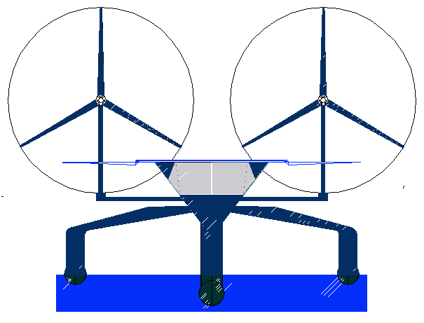
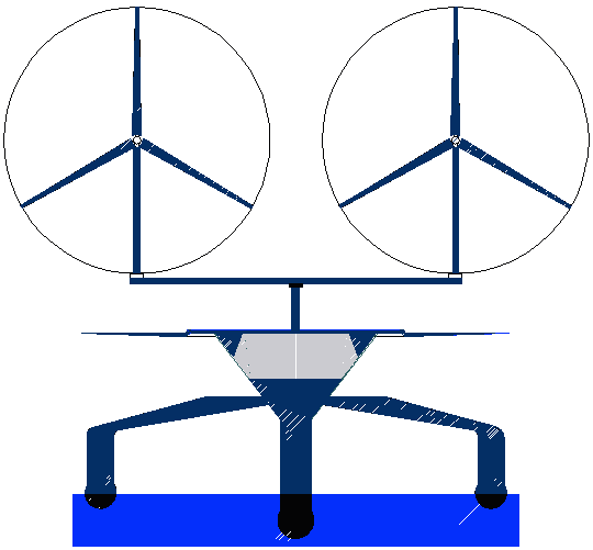
Compare the Bluefish ZCC design above with the Planetsolar front view in the previous paragraph. Both have solar wings extended, but the Bluefish ZCC has a wind turbine boom (in a mid position - left) and raised higher into the air stream (right) providing 8kW. The higher the turbines are placed, the more wind energy there is to capture. The boom can be lowered below the cabin line as protection during storm conditions and to prevent shading of the solar panels where the sun is behind the ship. Just how high we place the turbines is as always a practical design compromise. Using a lightweight structure and a long thin central hull with outriggers, reduces form and wave drag. The addition of wind generators increases the energy harvested to displacement ratio (EH/D) significantly to put this ZCC design into the 3-5 kW per ton range - and that puts us in the 7+ knot range for cruising speeds, aiming for 10+ knots average continuous with more swept area. The sun may not shine at night, but the wind keeps on blowing.
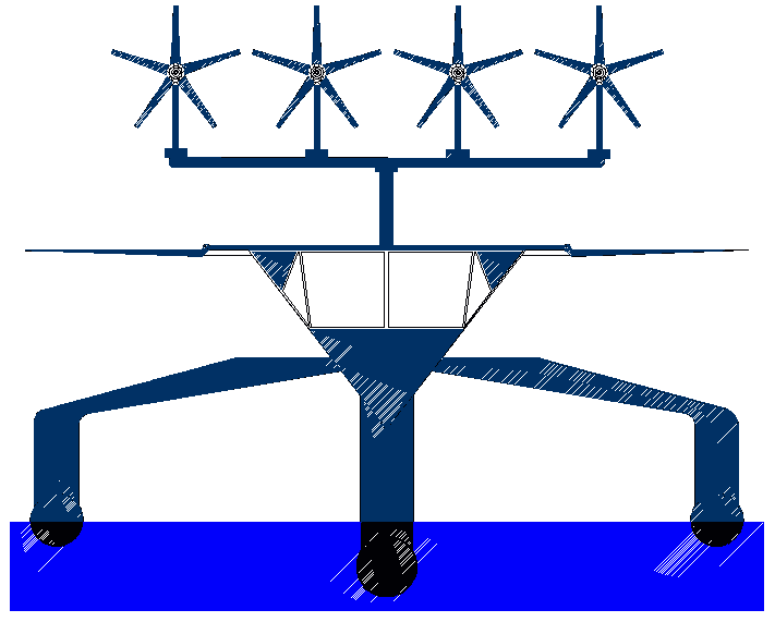
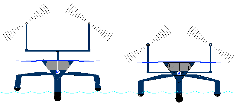
The Bluefish ZCC with 30kW wind (Ventera, Air Force or Bergey) turbines for greater operational speed and endurance (10knots). The more the swept area of the turbines, the more important it is to have effective automatic controls. The final EH/D figure will all depend on materials/components used - which is why this research is so badly needed. If you are interested in collaborating to develop this concept into a fully functional prototype, please contact us today. See the Horizon 2020 call for water transport proposals. Automatic, or robotic control of the harvesting devices is also important to maximize energy for propulsion, without the need for a crew to constantly make adjustments. The harvesting apparatus need not interfere with the uses that such a craft is put to - once again it's all down to flexibility of mind. Modified designs will work equally well as cargo, cruise, or naval vessels. The design of this ship is © November 2013 and the technology patent applied for.
The Combat ZCC with 40kW (Ampair 2x20) wind turbines [low operation mast height - left] [medium operational mast height - right]. This is a 50 ton vessel that is elongated, but retains the same low frontal area as with the merchant Bluefish ZZC platforms above. This battleship can be armed with a potent mix of torpedoes, SAM and Cruise missiles. The total energy harvesting capacity is around 176kW (235hp), giving an Energy Harvested to Displacement ratio (EH/D) of 3.52kW/ton (4.72hp/ton). The vessel is more efficient at collecting energy during darkness, reducing the battery storage needed, hence improving the potential payload. Larger versions of this format could be the emission free cargo ships of the future. The average cruising speed of this vessel will be higher from the longer hull 50m (163ft) hull on the waterline, giving a better speed/length ratio. The OAL is 56M (183ft). The sprint speed of this craft will be in the 20+ knot region - dependent on active hull deployment.
The cost of diesel fuel to operate this ship continuously for a year is approximately: .29gals/hp x 117 x 24 x 365 = $297,226.80 (£183,393.99) In ten years that would be $2.97M (£1.83M). Fuel for thought! In this calculation we have assumed for the sake of simplicity that the 235 horsepower harvested during the day is split 50/50 for day and night operation. In reality wind turbines operate just as well in the dark.
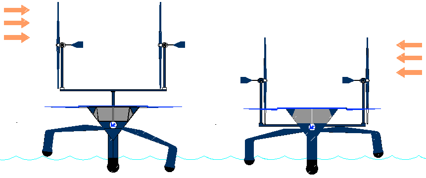
ABOVE LEFT: The Bluebird™ yacht shown above has mid-range (partially) raised turbines in a high beam wind, the vector causing roll to port. The autonomous trimming system compensates for this running condition using the active outriggers, by raising the starboard outrigger out of the sea and lowering the port into the sea. The main hull of the vessel then remains vertical. ABOVE RIGHT: A similar situation applies in this depiction, except that the wind is faster, as in a storm and coming from the other side. For this reason the turbine boom has been lowered to reduce roll, while the port outrigger has been raised out of the sea, to effect vertical running. By this means the ship can trim itself to harvest as much energy from the wind as it is safe to do, while still maintaining comfortable conditions for a crew. The design of this vessel is © August 2014 and the technology is patent applied for.
ABOVE LEFT & RIGHT: The same Bluebird™ yacht is shown here in a head on (or following) wind. Here the conditions are such that the active hulls must be in the sea to give a comfortable horizontal ride for any crew - or simply to maximize on energy harvesting - especially from the solar panel arrays. You will come to see that the active hull and energy harvesting systems are interdependent. The design of this vessel is © August 2014 and the technology is patent applied for.
ABOVE LEFT: In this picture, conditions are such that the Bluebird™ yacht hull is balanced so well that it does not need to have either the port or starboard outriggers in the sea as stabilizers. This will reduce the running drag of the vessel to the absolute minimum (as a mono-hull) - unfortunately, not all of the time. We cannot explain here how this is achieved because of patent publication laws, that would otherwise prevent grant. ABOVE RIGHT: Compare the wetted surface area of all three hulls in the water, with the single hull on the left. The design of this vessel is © August 2014 and the technology is patent applied for.
TRANSIT EXAMPLES - The above table illustrates one of the most likely ocean awareness expedition routes that could be undertaken by the Elizabeth Swan, showing the time elapsed in days for 7 knots average cruising speed, including times for 5 and 6 knot averages - allowing for 10% downtime and 36 days in ports. Hence, although the objective is to reduce the current solar circumnavigation record from 584 days, the event in not an outright non-stop yacht competition in the offshore racing sense. It remains to be seen how accurate such a prediction might be.
WHAT'S AVAILABLE IN THE MARKETPLACE?
The above vessel designs are based on what is currently available commercially. It may be that some of the heavier turbines featured below might be adapted to marine use, by replacing one material with another, etc. For example, the heavy towers used for land and offshore installations would not be used on a ship. This is one area of research where the Bluefish ZCC project is unique - provided that we get the support we need to be able to put theory into practice.
Compared to 20 years ago, nearly all modern designs are so much more efficient. The evolution of these machines for transport is the next hurdle to create fresh markets for this exciting technology.
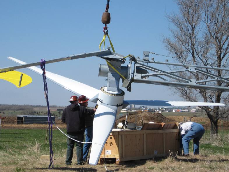
WIND TURBINE BLADES - Just like their full grown offshore counterparts, the swept blade area determines how much electricity you can generate. These are the wind turbines for the SeaVax large scale feasibility study.
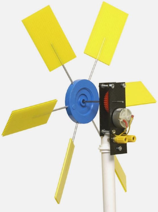
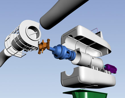
This is a simple kit that is available from an educational supplier, that turns an electric motor of the kind used in models, into a generator, by using six paddles made of corrugated plastic board attached to a yoke that then drives the motor via a nylon gear to increase the ratio of motor turns to windmill turns. Apart from the materials and design of generator the layout is much the same as with the big boys below.
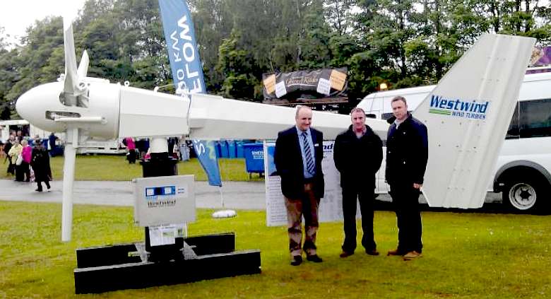
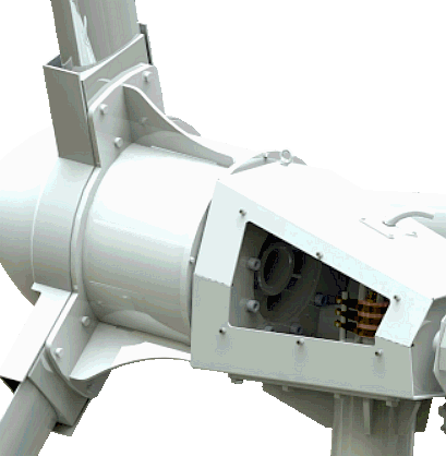
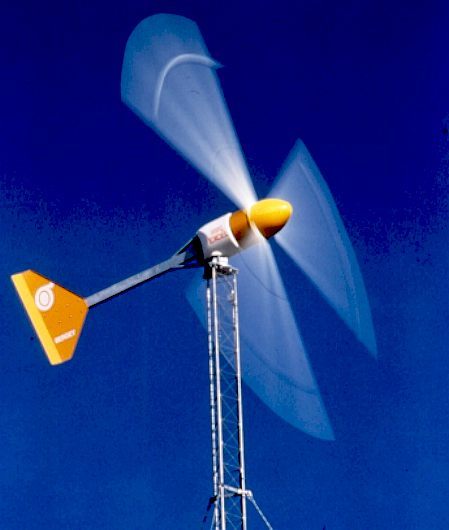
WESTWIND/AMPAIR
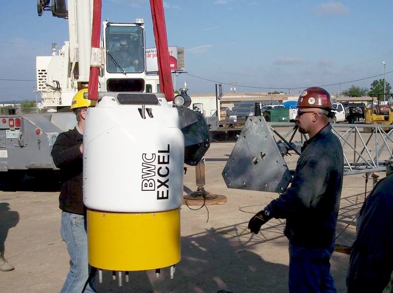
This company builds 3kw - 20kW wind turbines that may be suitable for the Bluefish ZCC.
The 20kW
model was originally released for commercial production in mid 2000 after three years
of field testing stage at Murdoch University's Energy Research Institute
in Western Australia - working with ACRE (Australian Centre for Renewable Energy). This association
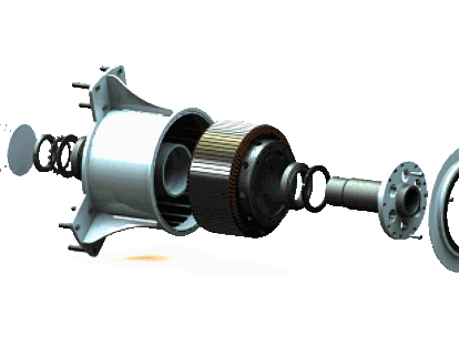
yielded a machine designed and constructed with leading edge technology throughout
- especially the generator and power controller.
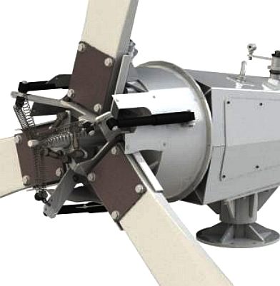
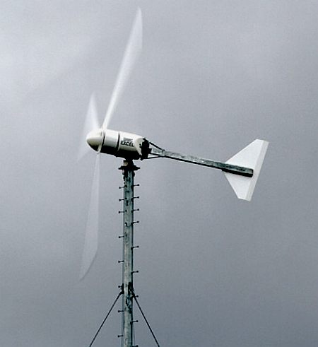
The weight of the tail boom provides a restoring force to turn the turbine back into the wind as the gust passes. Such a design is known as passive control and does not use electronics or actuators which may have a lesser lifespan than a mechanical fail-safe.
Automatic control of wind turbines is already a given. For transport situations existing sensors may be used to provide autonomous trimming of turbine height - in relation to ocean conditions.
WESTWIND 20kW SPECIFICATIONS
Cost: Around £35,000 excluding ground works
WESTWIND / AMPAIR CONTACTS
Ampair Energy Ltd. http://www.ampair.com/
Westwind
(J A Graham Ltd) BT29 4TF, Co.Antrim Northern Ireland
VENTERA
10kW WIND TURBINE – Model VT10-240
BERGEY 10kW WIND TURBINE
SPECIFICATIONS
The Bergey 10kW wind turbine in action and being installed
FUTURENERGY UPWIND AIRFORCE 10kW WIND TURBINE
(coming soon)
COMMERCIAL SHIPPING
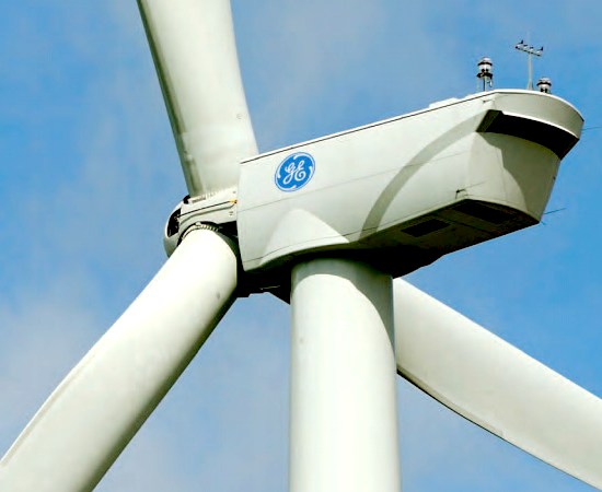
Imagine now that we have demonstrated the Bluefish ZCC and that we have ironed out the kinks at 140 feet (42.7m). The next stage of development would be to try out wind turbines on cargo ships and oil tankers of 300 feet (91.5m). If that came to pass, we'd be looking for turbines with megawatt outputs rather than kilowatts. The output of the enormous diesel engines that are used on oil tankers is phenomenal. Some 14 cylinder (38" bore) models weighing 2300 tons produce up to 109,000 hp. That is roughly 80MW or 20 of the GE 4MW units shown below. By reducing ship velocity just a few knots only 12 4MW units would be required.
In 2014, General Electric surpassed the Danish wind power company, Vestas, to become the world’s biggest wind turbine manufacturer. Twenty of these rotary leviathans would be needed to propel the biggest oil tankers in the world. That is not as bad as it sounds, provided that the correct controls and configuration are used.
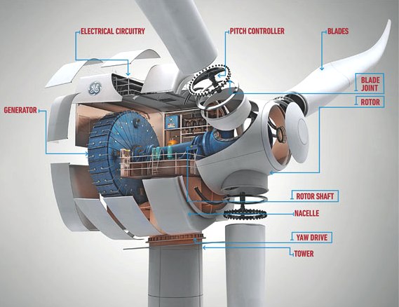
GE - GENERAL ELECTRIC
GE Wind Energy is a branch of GE Energy, a subsidiary of General Electric. The company manufactures and sells wind turbines to the international market. In 2009, GE was the second largest wind turbine manufacturer in the world.
In 2002 GE acquired the wind power assets of Enron during its bankruptcy proceedings. Enron Wind was the only surviving US manufacturer of large wind turbines at the time and GE increased engineering and supplies for the Wind Division and doubled the annual sales to $1.2B in 2003. GE acquired ScanWind in 2009. In February 2011, GE also acquired Wind Tower Systems, LLC, a manufacturer of space frame wind turbine towers.
GE currently produces three types of wind turbines, ranging from 1.5 MW to 4 MW. The newest turbine by GE, the 4.1 MW wind turbine (also called GE4.1-113) is the only offshore wind turbine model currently manufactured by General Electric. The offshore GE 3.6 SL was discontinued, but its installations remain in operation at the Arklow Bank Wind Park.
HORIZONTAL OR VERTICAL AXIS?
Wind turbine generation has advanced considerably when it comes to static wind farms, with horizontal three bladed mills (HAWT) being the most popular, but with some interest in vertical axis turbines that have lower start-up speeds and are quieter. It all depends on the application. Vertical mills are at the moment heavier and more expensive per watt generated, tending to rule them out for transport, but they are potentially more rugged in high winds and are said to work better in confused airflow. It is certainly worth experimenting with both designs:
1. The power to weight ratio of a typical vertical axis machine is in the region of 15 watts per kilogram. 2. The power to weight ratio of a typical horizontal axis machine is around 25 watts per kilogram.
These statistics are as of date of publication and do not rule out vertical axis machines, where other factors, such as stall speed may offset some of the weight disadvantages.
UNCONVENTIONAL HAWT MACHINES
TWIN BLADED ROTOR
China
Corp's 2-bladed wind turbine incorporates complementary technologies such as independent blade and tower flexibility for improved load damping
characteristics. This allows a more compact and lightweight transmission
system combining to reduce vibration and overheating, lower installation and
costs, improve service life and all being equal, extend the generated output lifecycle of the product.
GC China Turbine Corp.
TURBINE LAND VEHICLES WORK JUST FINE
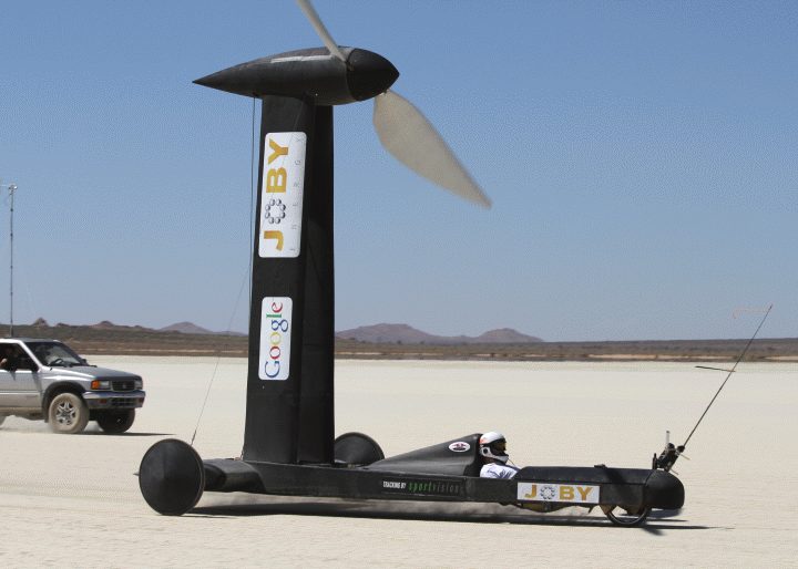
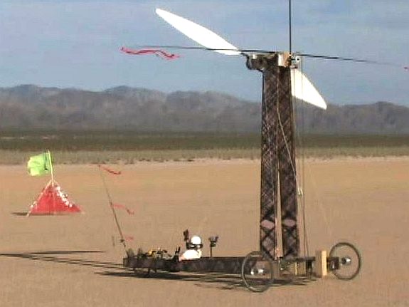
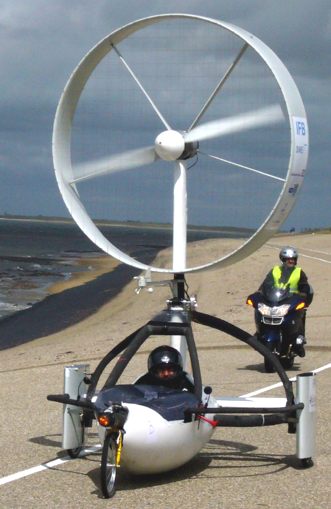
Wind-powered mechanical vehicles use wind turbines installed at a strategic point of the vehicle from which wind energy is converted into mechanical energy through gears, belts or chains, causing the vehicle to propel forward. They are not in mainstream use yet, but many schools have begun researching the new technology as part of their curricula. The Blackbird below uses chain drive to the driven wheels, the Ventmobile uses a wind turbine generator to drive electric traction motors.
The Google sponsored Blackbird (faired on the left, bare chassis on the right) which in 2010 successfully achieved more than 2 times the speed of the wind downstream, then in 2011 reached close to 3 times the speed of wind, suggestive that into the wind 1.5 times the speed of the wind is theoretically possible for the Bluefish ZCC, save that water drag is much higher than road drag from bearings and wheels. Don't try this at home children.
Left: the "Inventus Ventmobile" at the Aeolus electric formula zero land race 2008. Right: On March 26 2009, on the ‘dry’ Lake Ivanpah, the Greenbird driven by British engineer, Richard Jenkins, smashed the world land speed record for wind powered vehicles. The Greenbird clocked 126.1 mph (202.9 km/h) eclipsing the American held, record of 116 mph, set by Bob Schumacher in the Iron Duck in March 1999 at the same location.
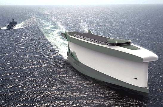
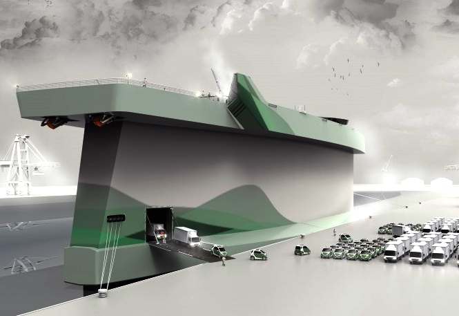
OTHER WIND BASED DEVELOPMENTS ON THE DRAWING BOARD - VINDSKIP by LADE AS
From
Norway, LadeAs claims that it doesn't matter how efficient we make their engines or how many solar panels we install on their decks, the world's largest cargo ships
- those water-bound leviathans on which international trade depends - will require massive amounts of
fuel
[dependent on hull
design] for the foreseeable future.
They claim that their conceptual super-carrier could potentially save billions of barrels of
diesel (bunker fuel) every year just by harnessing the wind.
Given that the Vindskip concept has yet to get off the drawing board, nobody's actually all that sure it will be feasible in real world scenarios. But if it does work out, the Vindskip design will be a fuel efficient vessel to and could very well change the face of international trade.
LadeAS’ fuel-efficient ship concept could revolutionize the overseas cargo shipping industry and reduce fossil fuel use by millions - if not billions! - of barrels per year.
The designers at LadeAS, the Norwegian designers have employed “lifting body” aircraft design, using the vertical foil shape of the main hull to generate positive lift as the engine pushes the wing shaped superstructure forward. In the Vindskip, the hull is shaped like a giant sail which, according to its designers, generates a forward thrust towards the apparent wind (the “wind” created by the forward progress of a vehicle that’s felt by its passengers). There are though obvious problems to overcome, the first of which is working out if the extra hull material needed for a giant vertical wing will add to the mass of the craft (mass=hull drag) to offset the theoretical advantages - or whether it would be just as advantageous to put wing-sails onto a conventional cargo hull, as in the Walker Wingsail system?
The design concept was sufficient for the company to apply for international patents, and the company suggests that a computerized navigation system running a number of complex algorithms from GPS and weather satellites could help Vindskip captains to plot the most fuel-efficient shipping courses “on the fly.” That means that this simple technology will, on its own, rival the more expensive fuel and emissions reductions of ships like Nissan’s solar-diesel hybrid car-hauler and Viking’s LNG-engined cruise ships (the same engine, which, it should be noted, will be used by LadeAS).
The Vindskip concept seeks to achieve savings as a percentage, which we of course applaud, whereas, the ZCC concept seeks to provide 100% energy for ships from nature - harking back to the days of sail, but using wind and solar energy in a new way that does not require sail manipulation and also has an energy reserve. It is good to see so many international companies thinking of wind as an energy source. We hope to be able to contribute to the process with help from the EU, should that be on their agenda.
LINKS & REFERENCE
http://en.wikipedia.org/wiki/Unconventional_wind_turbines http://www.ampair.com/news/ampair-announces-exclusive-negotiations-to-acquire-westwind http://www.venteraenergy.com/product-specs/ http://en.wikipedia.org/wiki/Wind-powered_vehicle http://www.kitves.com/ Massive-cargo-ship-will-harness-the-wind http://cleantechnica.com/2013/09/26/vindskip-fuel-efficient-ship/ http://en.wikipedia.org/wiki/Wind_speed http://en.wikipedia.org/wiki/Wind http://en.wikipedia.org/wiki/Wind_triangle NedWind Rhenen bV NW 43/500 (Turbine), Nedwind website. 27 January 2013. Why 2-Blade?, GC China Turbine Corporation website. 27 January 2013. (WO1992012343) Wind Turbine, Patentscope website, 1992. Furling tail windturbines (page 18) PDF "Power from the Winds." Popular Mechanics, June 1954, pp. 124-125. Yavuz Ali Şener "Gelibolu Modeli" Ruzgar Turbinlerinde Verimlilik Parametrelerinin Arastirilmasi ("Gallipoli Model" Investigation of Wind Turbines Efficiency Parameters) Project No.: Misag-7, Ankara, 1995. (PDF images in Turkish) Ward, Logan. Windbelt, Cheap Generator Alternative, Set to Power Third World, Popular Mechanics October 1 2007 Sofge, Erik. Shawn Frayne Makes Another Leap in Wind Power: Breakthrough Winner Update 18-12-2009 Description of several types of wind turbines –including piezoelectric Power generation system utilizing wind draft from vehicular traffic Mark Oberholzer's roadside Darrieus wind turbine design BWEA website, (account required, scroll down to SPERBOY) Young, Kathryn (2007-08-03). Canada wind farms blow away turbine tourists Edmonton Journal "New US Rooftop Wind Turbine Lab". Renewable Energy World. 2009-07-07. Leake, Jonathan (2006-04-16) Home wind turbines dealt killer blow London: The Sunday Times http://gas2.org/2012/02/26/new-lng-viking-cruise-ship-cuts-emissions/ http://gas2.org/2012/01/31/nissan-builds-solar-diesel-ship-to-transport-eco-cars/ http://en.wikipedia.org/wiki/Lifting_body http://en.wikipedia.org/wiki/Apparent_wind Hydroptere-The-worlds-fastest-sailboat-hoping-sail-Pacific-record-time http://gizmodo.com/this-massive-cargo-ship-will-harness-the-wind-with-its-1379898363
Solar House, BN27 1RF, United Kingdom + 44 (0) 1323 831727 +44 (0) 7842 607865
A - Z SAIL AND SOLAR ASSISTED BOATS & SHIPS
19 Jan 2014: If you are an eco entrepreneur, a campaigner for social justice or have a great green idea for making the world better, then we want to hear from you. Lucy Siegle introduces this year's Observer Ethical Awards and explains how you can nominate.
19 Jan 2014: Observer Ethical Awards in association with
Ecover. Britain is bursting with brilliant ethical ideas. We are world leaders in sustainability, from grassroots campaigns and education to scientific research. Unfortunately these ideas often don't get the air time they deserve. But then dealing with the causes of issues such as climate change and inequality has never been politically expedient. Lately activists who are ploughing on regardless and are successfully bringing some eco solutions into the mainstream have started to refer to the "green hush" that has descended as those speaking up for marginalised people, communities and landscapes are drowned out. The intention of this year's ninth Ethical Awards is to make as much noise as possible about the extraordinary people, projects and places that are bringing about ethical change.
Best in business
SUSSEX BUSINESS AWARDS 2014
EARLY DEVELOPMENT TEST MODELS - LINKS
Blackcurrant 1 | Blackcurrant 2 | Catamaran Hull Design Drag | SWASH | SWATH | Trimaran
|
||||||||||||||||||||||||||||||||||||||||||||||||||||||||||||||||||||||||||||||||||||||||||||||||||||||||||||||||||||||||||||||||||||||||||||||||||||||||||||||||||||||||||||||||||||||||||||||||||||||||||||
|
This page is Copyright © 2019 Bluebird Marine Systems Ltd. The names Bluebird™, Bluefish™, SeaNet™, SeaVax™ and the blue bird & fish in flight logos are trademarks. All other trademarks are hereby acknowledged.
|
||||||||||||||||||||||||||||||||||||||||||||||||||||||||||||||||||||||||||||||||||||||||||||||||||||||||||||||||||||||||||||||||||||||||||||||||||||||||||||||||||||||||||||||||||||||||||||||||||||||||||||