|
|
SEAVAX - ENERGY HARVESTING DEVELOPMENT PROGRAMME
|
|
|
|
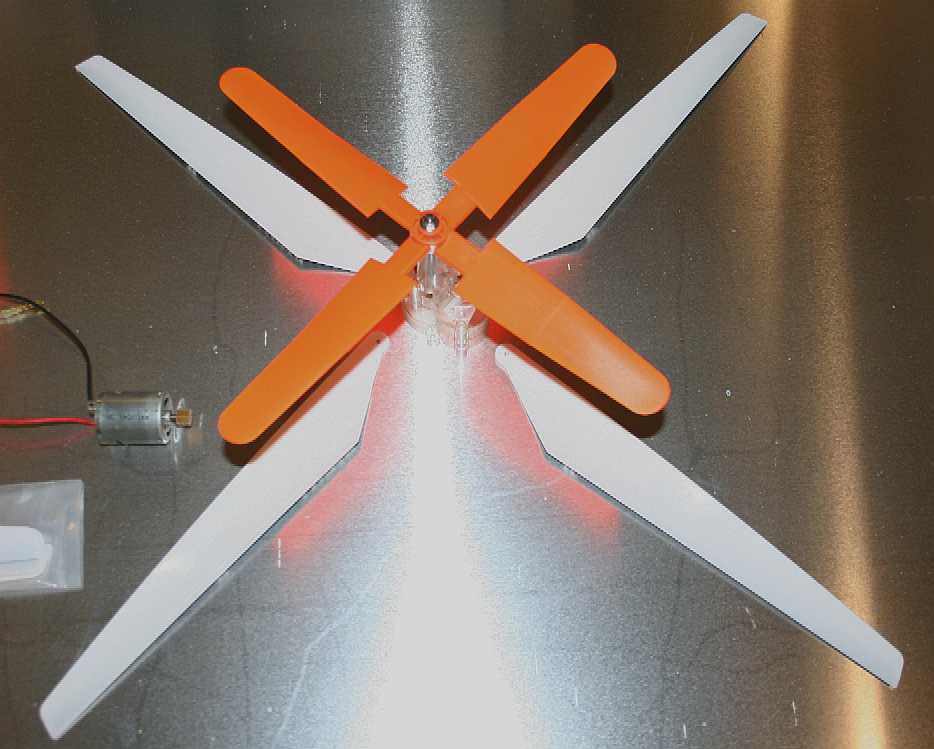
At the moment you can't buy an off-the-shelf 25-50 watt wind turbine with a very low speed startup, leaving us to a bit more creative DIY. Fortunately, there are some fairly efficient model helicopter blades that may do the job. We'll be using twin contra-rotating turbines that are on a yard (a transverse boom) that can be raised and lowered on a mast. Raise the boom to get the turbines into the faster moving air - and lower the boom to prevent shading of the solar panels, or to furl when high winds threaten the safety of the craft. You should note that the efficiency of these blades can be improved. They are not airfoil section!
WIND ENERGY
Wind is an abundant renewable source of energy that for transport purposes is woefully under used, mainly because of our love affair with diesel engines. The question is for how much longer should we ignore free energy from nature - when the technology to harvest it is available off the shelf. It was not long ago that all sea trade relied on the "trade winds" with clipper ships like the Cutty Sark plying their passage at respectable speeds approaching 15 knots. Then steam engines came into the frame burning coal. Hoisting and renewing sails was overtaken by the controllability of steam. Steam was in turn ousted by the convenience of diesel, and now diesel is considered dirty and expensive with MARPOL being enforced, triggering a move to liquid natural gas and dual fuel engines - so we may be about to come full circle, provided that we can convert wind energy and store it, to load level.
HOW MANY BLADES SHOULD MY WIND TURBINE HAVE?
The number of blades influences the efficiency of a wind turbine. 2, 3, 5 blade wind turbines are frequently used. It is known that the more blades used, the more reliable and safe the wind turbine is. They work more silently and are more efficient. The cost is an adverse factor though. Designs with 3 blades can provide 35% - 40% efficiency so that is a good start, we have used 4 blades for our development model for practical purposes.
Working
out what generator to use for a wind turbine can lead to information overload.
There are so many types of electrical machine out there and the market is still
in its infancy. Hence, dynamos and ordinary dc motors are being offered cheaply,
but of course they have brushes to wear out. Ignoring that for now - and just by
way of example, if you wanted to generate 2.5kW peak, you'd need a
motor/generator that has:
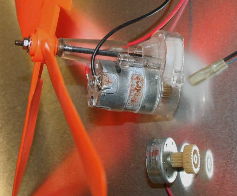
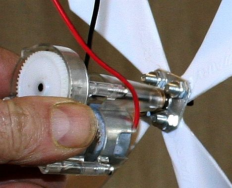
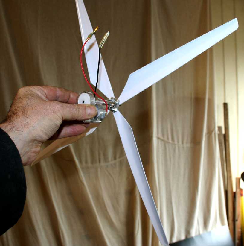
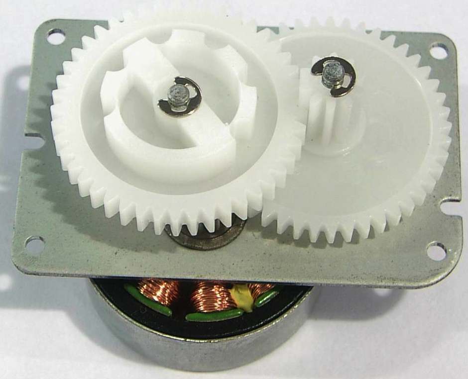
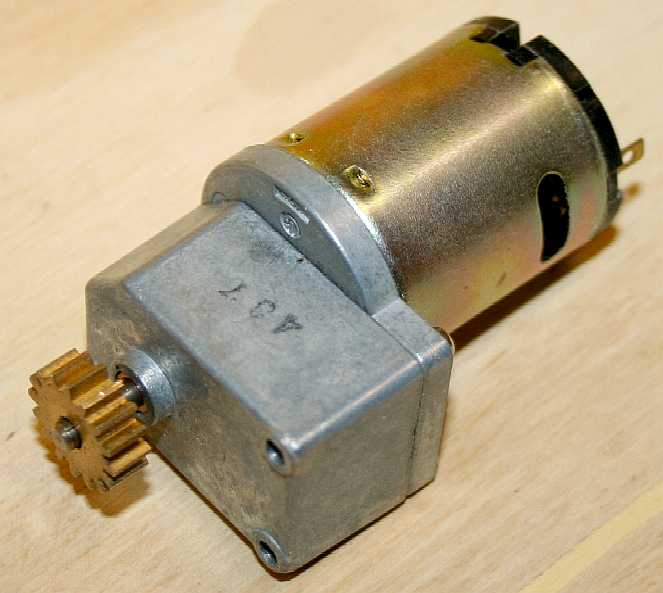
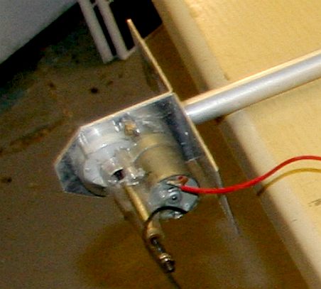
The motor/generator (dynamo) and gearbox arrangement for a very simple DIY wind turbine. We had to raid our store of small DC motors to find suitable candidates. It is very hard to find a small wind turbine generator for a 1/20th scale boat. In the end we had to mix and match our own and experiment with different motors, to use as generators (dynamos). Some of the best are the Swiss made Maxon motors. They are a bit heavy, but are reasonably efficient. We are also looking at the latest brush-less design model motors used in aircraft and helicopters, where, with a suitable diode bridge rectifier, we can create a miniature alternator. This is because alternators are more efficient than dynamos at producing electricity at slow speeds. We convert the AC current generated to DC for our batteries and motors. We are looking to generate 24-50 watts per windgen from a swept area per turbine of 0.65M, or 1.3M combined. If any person, company or academic institution might be able to help us improve on this figure, we (BMS) would appreciate a call.
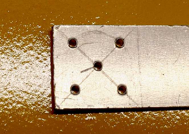
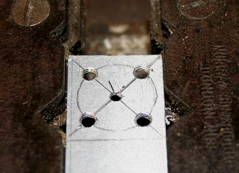
ROTOR HUB - Starting with some 4mm plate aluminium, we made our own wind turbine hubs. Marking out accurately is essential with 1mm or less for the pilot holes. If you have a lathe, you can get this pretty much spot on, but you need a blank to begin with. We made a couple of test pieces by hand to get the angles right. Threads are cut in the hub for 3mm and 4mm bolts. On reflection, 3mm would have been fine for all of the fixings. You'll need a jig to set the final angles. It's a bit like using a fletching rig for mounting flight feathers accurately on arrows - if you are into archery. If you don't get the balance spot on, the rig will vibrate like mad in high winds. If you don't fletch an arrow correctly it will not shoot straight. If you don't get the angle right on these blades, you might not generate anything at all (stall). We may move to steel hubs for endurance trials once we are happy with the performance of this development model.
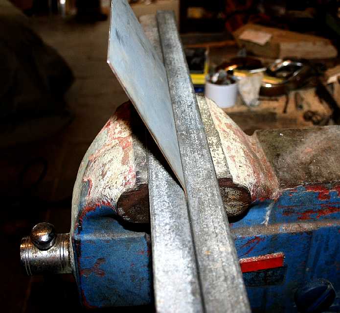
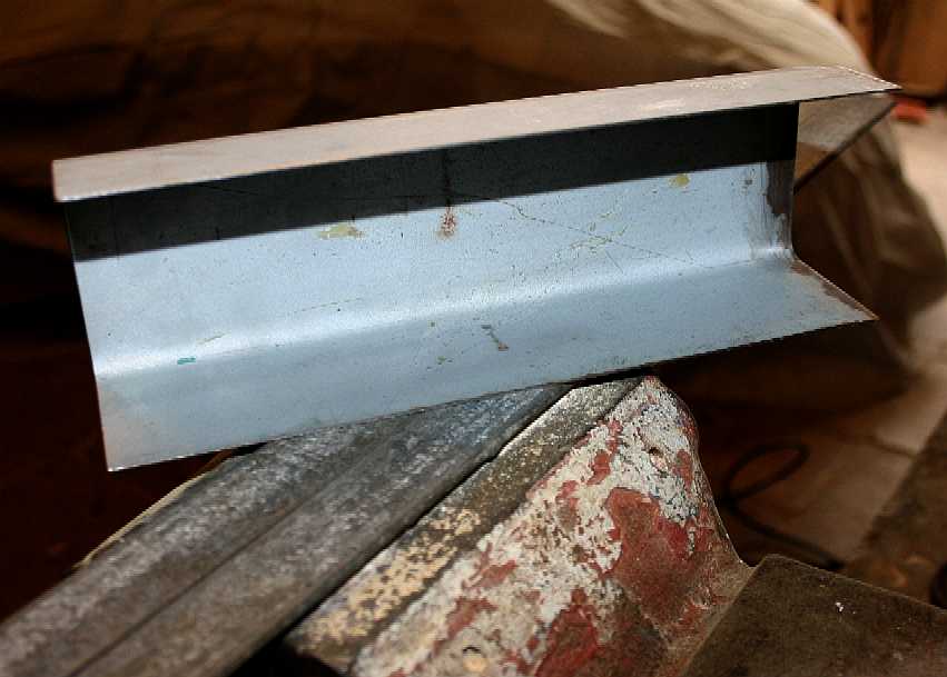
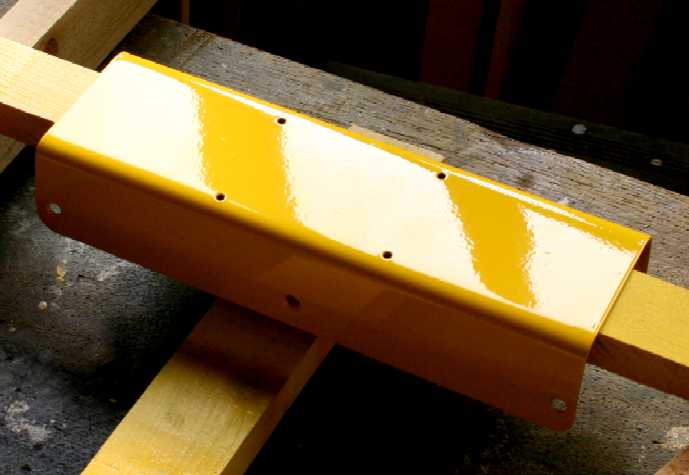
MOUNTINGS NEXT - Changing to steel for the mounting plate to the hull or more correctly, the prow of the ship. We took a sheet of mild steel from our stock used to repair vehicles, cut it to size, marked out the lines for folding and used our trusty 6" swivel vice with angle-iron formers to produce a 'U' shaped channel that will fit on the front of the robot's deck folding over and under the prow - as seen below.
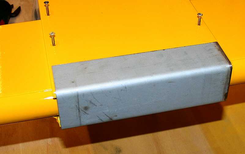
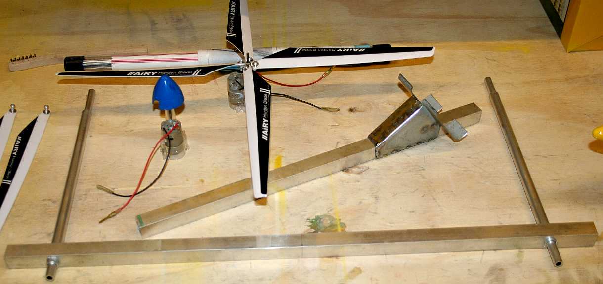
WIND TURBINE MOUNTING - That's good. A nice engineering fit, ready for the mounting holes to be drilled. This plate distributes the considerable loads from twin contra-rotating turbines to the hull structure. You can see the size of the blades below. Next we need a bracket from this plate, to mount the forward facing aluminium 'T' shaped mast, comprising a forward facing box section tube or bowsprit and a transverse boom or yard. A mast is usually a vertical tube (in the old days a log) that protrudes from the deck of a ship, reinforced with stays. Our mast protrudes from the deck ahead of the craft at less of an angle of a conventional bowsprit. Atop the bowsprit is a yard onto which the turbine poles (smaller upright masts) are mounted.
We are using a simplified version of the design that we have on the drawing board for a self leveling mast/boom (for the full size craft) that give us much greater changes in attitude - from almost the surface of the sea, to 12.3 meters (40ft) high above the waves (lower tip to lower tip) with 9.5 meter blades. The feasibility study will have adjustment effected by hand, the working robots will use hydraulics as the motive force, not that dissimilar to a JCB type earth mover, save that a JCB has a human driver and we have a program and electronic sensors. Okay, it's completely different.
WIND TURBINE BLADES - Just like their full grown offshore counterparts, the swept blade area determines how much electricity you can generate. We've been out in the wind testing the blade angles and comparing with the results from the much smaller orange prop seen above. Size matters. We've had startup at very low wind speeds, compared to the off-the-shelf items, using model helicopter blades. A helicopter saw free flight from as early as 1907. Focke Wulf produced the Fw61 helicopter in 1936 with limited success, but Igor Sikorsky produced the first practical single rotor helicopter with his VS300, then the famous mass produced R4. Now, you can buy a remote controlled copter for under £30.
The object of the autogyro and helicopter concepts was to reduce the runway take off space, or allow vertical take off. Some very clever chaps realised that by moving a wing at the same speed as an aircraft at take-off, or rather a smaller wing moving faster to give the equivalent swept area, an aircraft would lift into the air, even if the aircraft was stationary. The solution was to rotate a wing about an axis (shaft) affixed to the aircraft. Bingo! The helicopter was born and later the quadcopter, which we are using as a plastic scout for the SeaVax.
PATENT PENDING - IMPROVING THE POWER TO WEIGHT RATIO
One way to improve the power to weight ratio of a solar powered ship is to supplement energy from photovoltaic panels with energy that is captured from the wind, by converting that energy to electricity. In this way energy from the wind may be stored. Rotary sailing ships do not need to tack like ships using cloth sails that are beating to windward (sailing directly into the wind). Tacking at 30-45 degrees left and right of wind direction seriously reduces the efficiency of a sailing ship and complexity of vessel operations.
Development of this concept will focus on keeping the mass of the supporting structure down while maximizing collection area, taking into consideration safety and stability. A unique system of auto-tacking is employed where the turbines face directly into the wind in formation, regardless of the direction of travel of the vessel. The clipper ship captains of old would be green with envy, not having to tack or constantly adjust their sails. This too is a development area.
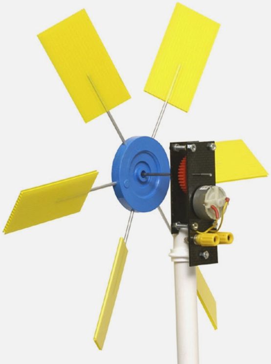
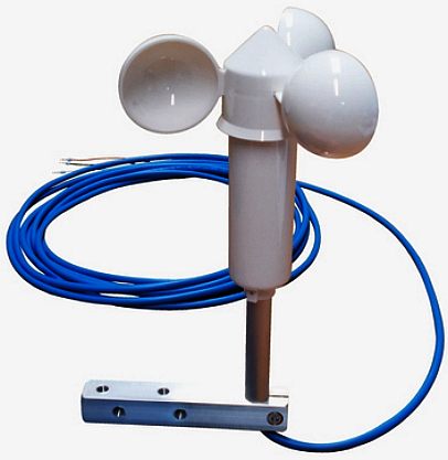
This is a simple kit that is available from an educational supplier, that turns an electric motor of the kind used in models, into a dynamo type generator, by using six paddles made of corrugated plastic board attached to a yoke that then drives the motor via a nylon gear to increase the ratio of motor turns to windmill turns. Apart from the materials and design of generator the layout is much the same as with the big boys below.
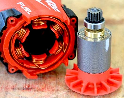
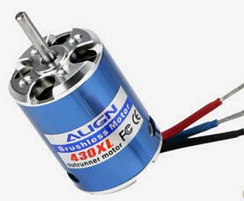
One thing that should be obvious, is that using brushed motors as generators is nowhere near as efficient as using an alternator. You cannot of course buy alternators at this scale. You can though substitute a brushless motor and use simplified (3-phase bridge rectifier made up of 6 diodes) electronics to turn the alternating current produced into direct current. You'll need dc to charge batteries. The bad news is that the brushless motors used in models, spin rather faster than we'd like for a wind generator.
WHY
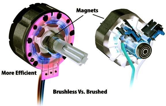
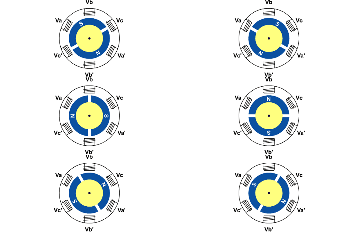
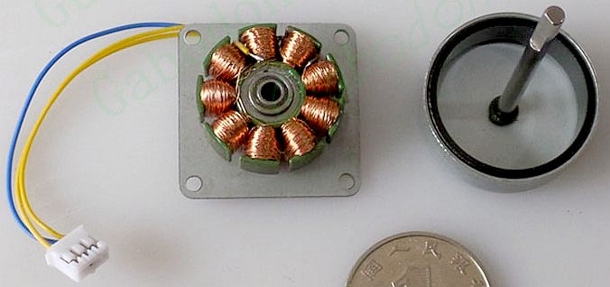
USE BRUSHLESS GENERATORS? - A brushless motor/generator loses the brushes and the commutator and the locations of the magnets and windings are reversed: The magnets are on the conventional motor shaft and the copper windings of the armature are fixed and surround the shaft. Instead of brushes and a commutator, a small circuit board coordinates the energy delivery to the windings.
Brushless motors are typically around 80% efficient, brushed motors such
as a typical Mabuchi
unit are nearer 50%.
Brushless motors can be more powerful overall. Because the copper windings are on the outside of the motor configuration, there is room to make them larger. Brushless motors also don't have the friction and voltage drop that brushes create by dragging against the spinning commutator. This physical contact results in a continuous energy loss during the operating process. Since brushes are designed to rub against revolving internal motor parts, they wear out in time. That’s just the way it is, and if brushes aren’t replaced in time, any motor will be ruined with continued use, but one of the main advantages is that the brushless motor is around 40% more efficient.
Performance - Brushless motors run cooler, quieter, and with less vibration. The absence of brush arcing reduces radio frequency and electrical noise that can interfere with electronics. Unlike brushed motors, which are often wired to be more powerful running forward, brushless motors are equally powerful in either direction.
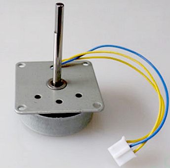
Miniature three-phase
alternator specifications: This product is a three phase ac generator
that can light up am LED lamp. The product is suitable for micro wind power, miniature hydraulic hand friction power
system and as an educational teaching tool for schools and colleges.
Design - Brushless motors have a greater power density, so for a given level of output they can be smaller and lighter than conventional motors. Since these motors are electronically controlled, it’s easy to add performance features such as multiple speed settings, soft-start, and soft-fade when the tool is switched off.
Problems - The difficulty is sourcing the correct output alternator for the blade diameter to match your project. There is as yet no range of mini alternators that are efficient.
THE REAL DEAL
A
number of companies now build 3kw - 20kW wind turbines, saving us the
bother of development. One potentially
suitable machine for our full size SeaVax is the 20kW
model originally released by Westwind for commercial production in mid 2000.
This model was tested for 3 years at Murdoch University's Energy Research Institute
in Western Australia.
THE FULL MONTY - Automatic control of wind turbines is already a given. For transport situations existing sensors may be used to provide autonomous trimming of turbine height - in relation to ocean conditions. We'll be using hydraulics (electro-hydraulic) for this function, except in circumstances where electro-mechanical drives are more suitable.
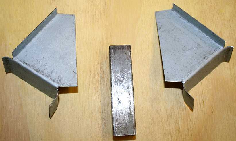
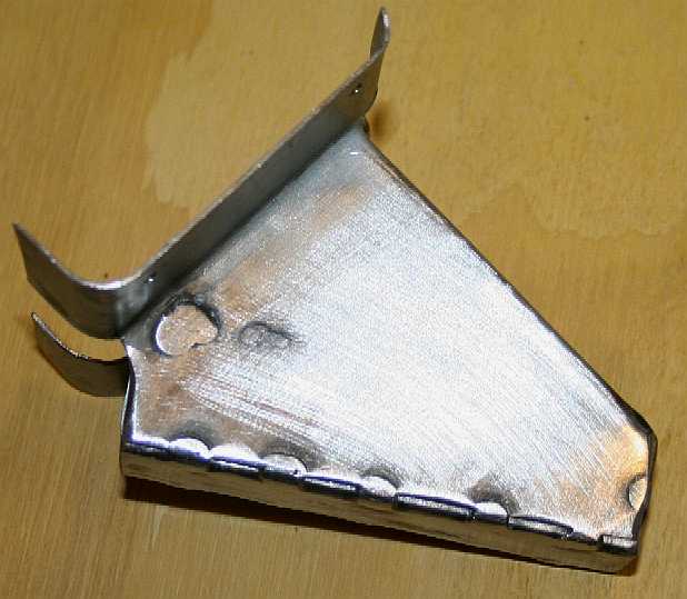
STEEL MOUNTINGS - We need to make a collar or guide that our aluminium mast can slide up and down inside without sideways movement. We are not making the more complex self-leveling mast that will be used on the full size ship, where hydraulics will be preferred as the motive medium. Here we made two mirror image plates from thin sheet steel. They will shroud the box section steel tubing seen in the middle of this photo.
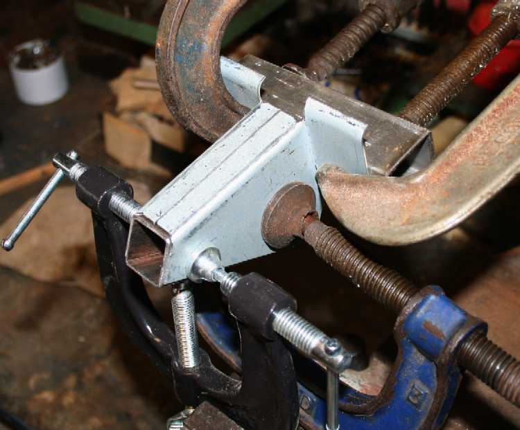
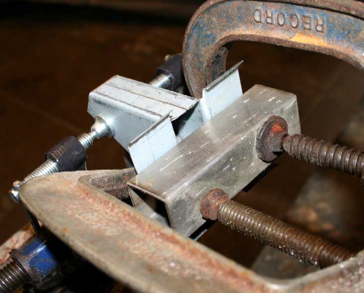
VICE SQUAD - We decided not to make a jig for this assembly, but to clamp the steel parts together with our trusty selection of 'G' clamps - all held in position on a sturdy 6" vice. A solid vice is the mainstay of fabrication for most small workshops. We also have a traditional anvil, but it rarely sees any action. Though it is eye-catching. Keep your threads well oiled and these clamps will last a lifetime.
CLAMP IT - When welding thin section steel sheet to thin wall tubing, close fit up is essential. We'll be MIG welding this component for speed. If you wanted a showpiece, use TIG welding.
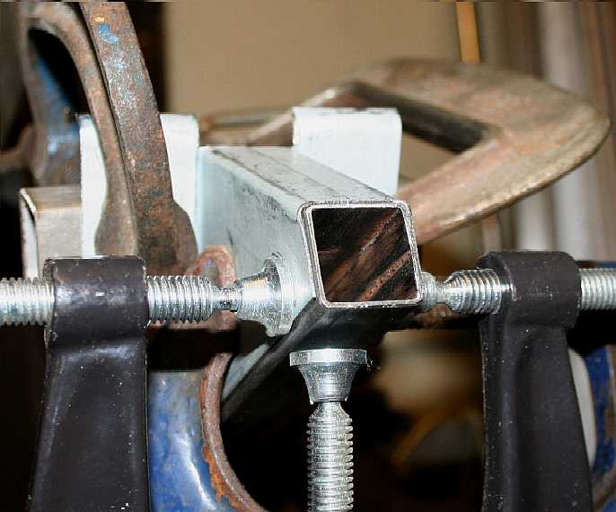
KEEP IT SQUARE - We are often asked how to be sure a hand fabricated frame is square. The answer is to use flat surfaces and set squares against which to clamp parts together for welding. Here you can see that a 30x30mm steel box section was the flat surface we used to clamp the two formed steel plates to the 20x20mm box section steel collar. Note the 'Record' 'G' clamps with square section threads. Quality like that is hard to find these days, because it is mostly down to price.
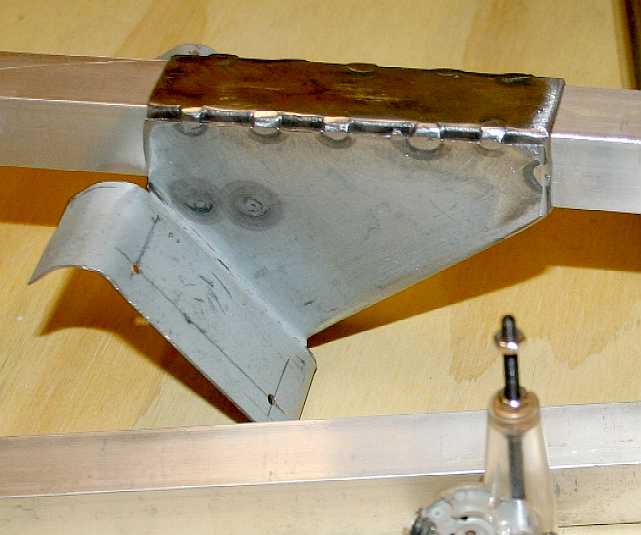
PENETRATION - Be sure that all steel parts are clean before welding. Set up the MIG for thin steel (we used 50 amps on our trusty SIP welder) to ensure complete penetration of the weld. You need to see signs of the molten metal puddle on the reverse side of the sheet to the weld side - as you can here on the left, where we put a couple of spots on the inside of the plates. After welding we made sure there was no distortion by inserting our aluminium mast. It was a lovely slide. If not, you may have to fettle a little, or, worst case scenario - make another bracket and revise the welding order.
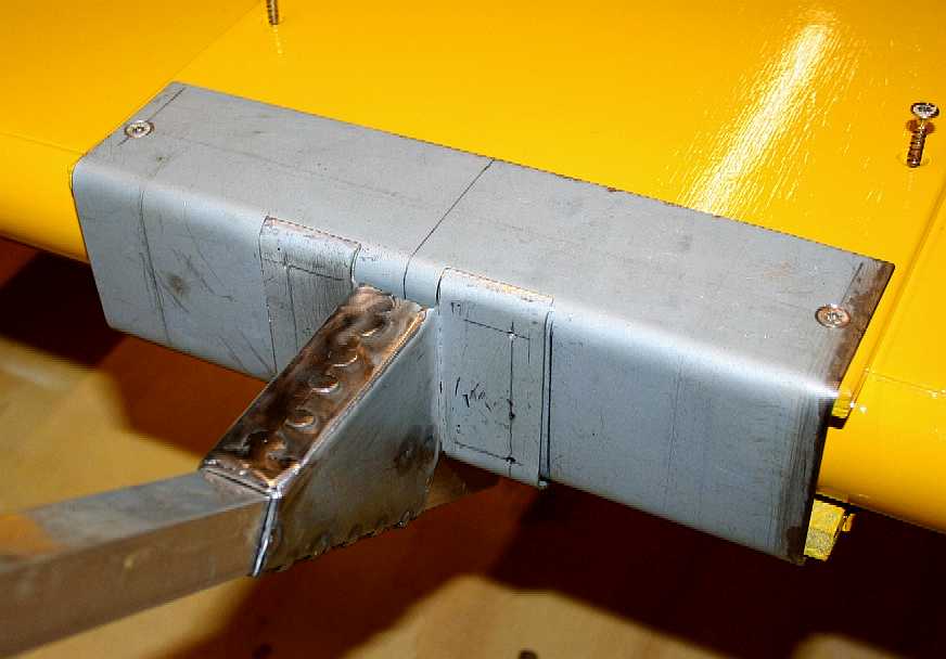
DECK MOUNTING - With the deck mounting channel screwed in place, we can drill and tap the holes to be able to bolt the mast (bowsprit) collar in position. We'd suggest a jig at this stage (especially if working full size) to be sure the mast is upright. The angle of this spar is ideal for the mounting of a figurehead. If we do stretch to a figurehead, it is likely to be loaded with instrumentation.
DECK MOUNTING - Being made of steel, a full primer, undercoat and topcoat is needed for the deck/prow of the boat.
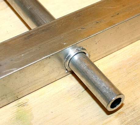
MACHINING - Here you can see the transverse boom (or yard) and generator mounting poles (masts), with a central spindle inserted. The aluminium poles should be an interference fit ready for welding to the yard. This will ensure that the poles are upright. The spindle should rotate freely inside the poles, even without bearings. Bearings are surfaces or moving surfaces that are designed to reduce the friction that would normally wear quickly, from metal sliding over metal. Reduced friction also means a smoother movement. Bearings are normally lubricated, especially ball bearings. Nylon is a good example of a bearing material that needs no lubrication.
PARTS ASSEMBLY - Here we have the mast and collar, the boom, poles and spindles and the wind turbine generators. We now have to make the generator to spindle mountings and the synchronizing rod that will keep both turbines balanced when facing into the wind. This is of course an innovation and we think most probably another world first. It goes without saying that there should be plenty of clearance between blades and between the yard or boom, and 360 degrees of rotational freedom for the wind turbines - so that the boat direction is independent of wind direction - as the turbines track the wind. Rotary sailing ships are nothing new. Peter Worsley pioneered his patented concept more than 20 years ago. This application is a development of that technology and a move away from direct mechanical drive for greater operational flexibility; essential for unmanned ships. Just imagine how many men it used to take to operate a tall sailing ship. With this system we need none - and that is where robotics is so helpful. Arduino to the rescue.
MAINSAIL WINCH - [LEFT] Motor and gearbox that is to be used to raise and lower the boom. [RIGHT] Adapter plates onto which the generator gearbox mounts to the revolving mast shafts. These adapters will be shaped to reduce turbulence around the generating blades.
COMMERCIAL WIND POWERED SHIPS
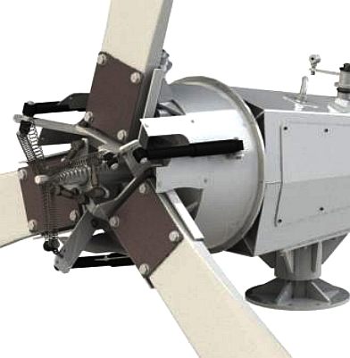
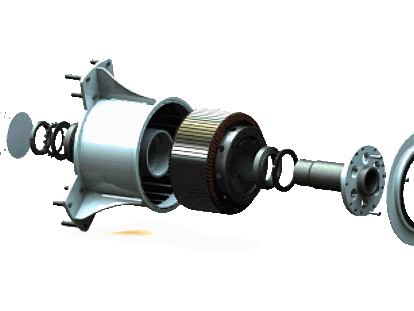
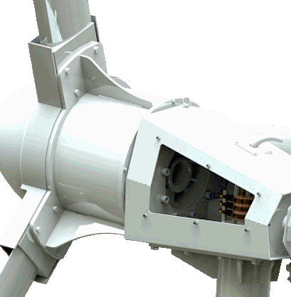
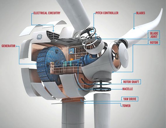
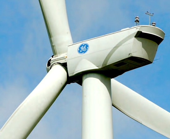
Imagine now that we have demonstrated the SeaVax and that we have ironed out the kinks. That might pave the way for wind turbines on cargo ships and oil tankers. If that came to pass, we'd be looking for turbines with megawatt outputs rather than kilowatts. The output of the enormous diesel engines that are used on oil tankers is phenomenal. Some 14 cylinder (38" bore) models weighing 2300 tons produce up to 109,000 hp. That is roughly 80MW or 20 of the GE 4MW units shown below. By reducing ship velocity just a few knots only 12 4MW units would be required.
In 2014, General Electric surpassed the Danish wind power company, Vestas, to become the world’s biggest wind turbine manufacturer. Twenty of these rotary leviathans would be needed to propel the biggest oil tankers in the world. That is not as bad as it sounds, provided that the correct controls and configuration are used. Vestas was founded in 1898 as a blacksmith shop in western Denmark. They started producing wind turbines in 1979, and have since gained a market-leading position with more than 64 GW of installed wind power and more than 42 GW under service globally.
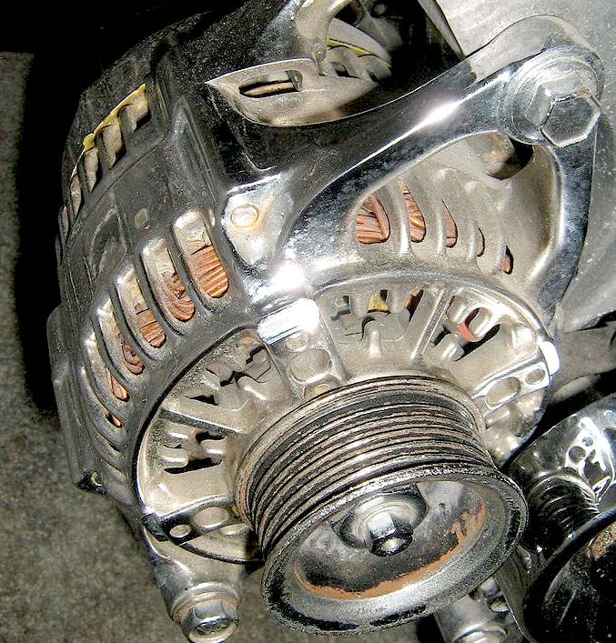
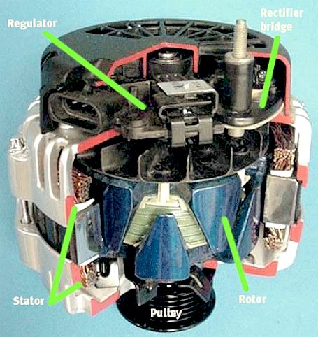
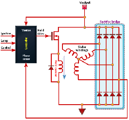
AUTOMOTIVE ALTERNATORS - Dynamos were the Achilles heel of passenger car charging systems right up until the 1970s, because they were terrible at producing power at low engine revolutions. Many vehicles could not charge the batteries properly, especially on short city runs. Six volt systems gave way to 12 volt systems for a part cure. The final solution came in the form of the automotive alternator and power electronics. Some examples of vehicle alternators and a circuit diagram are seen above.
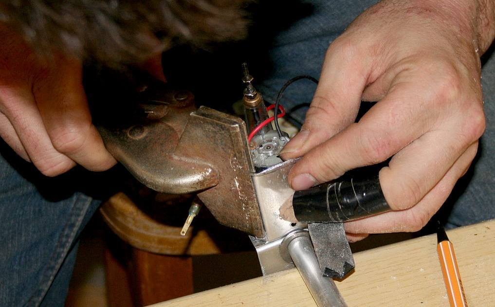
FAIRINGS - Having mounted the motor unit on spindles that rotate freely, we then need to shape the structural mounts to streamline the generators. This done by hand using ordinary garage type tools. Chris accidentally put a drill into his finger while making some ally sheet metal parts. If he can do it, you can do it. So be very careful and use grips whenever you can.
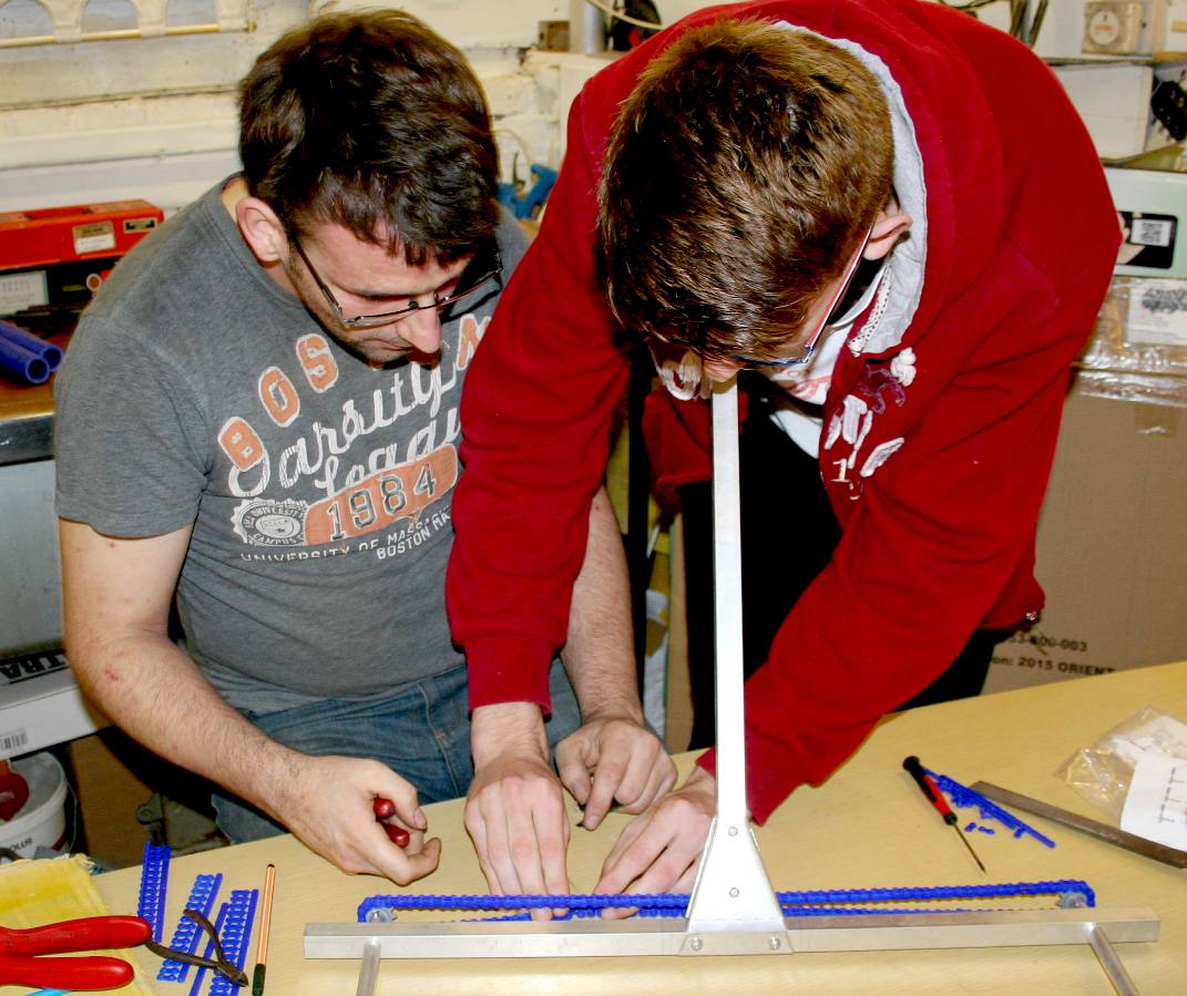
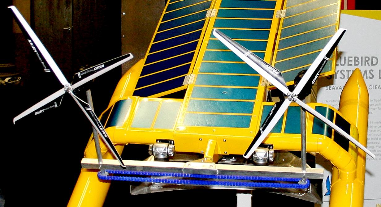
MENTORING - Chris and Jamie working together on assembly of the test-rig chain. We tried a number of different designs before adopting this configuration. We are unable to show the rig that furls in hurricane winds because of patent laws. Hence, the unit that you are looking at is not the all singing and dancing robotic boom and masts that we will be using with the 20kW full size turbines. They will though do the job for now to allow up to collect performance data.
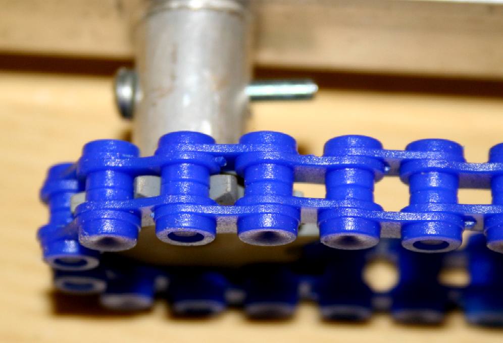
NYLON CHAIN - This type of chain is ideal for robot engineers who need to test the theory of a mechanism before moving on to a more robust prototype. This chain is surprisingly strong and good value but a little bulky and very brightly coloured.
TEMPORARY RIG - We tightened this rig up for the Innovate 2015 show way past practical operational tensioning, to prevent visitors from moving the windgens just by walking past. They are that sensitive. When correctly tensioned the chain needs additional support to prevent droop. Those supports are not shown here. The chain synchronization ensures that the wind turbines work more efficiently. Other methods to achieve the same result are possible but need more precise engineering and time in making parts than we had in the run up to Old Billingsgate.
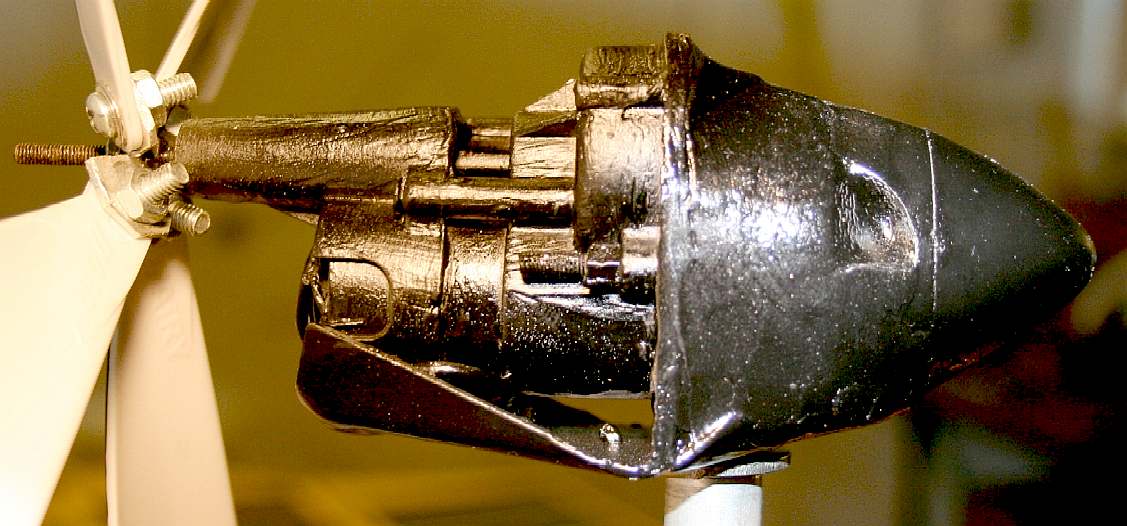
WIND TURBINES - Close up of the motor and gearbox with blades attached. We have added a fairing at the front of the assembly that could be more streamlined, but first we'd like to improve the efficiency of the units by going over to brushless technology.
CLEAN TRANSPORT OF THE FUTURE - Once this system is proven for workboats, it could be fitted to pleasure yachts and even cargo ships of the future - breaking our reliance on climate warming internal combustion engines.
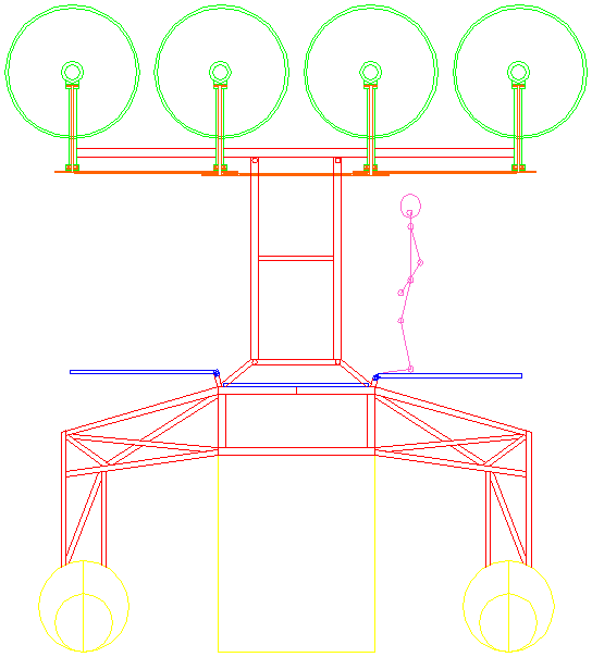
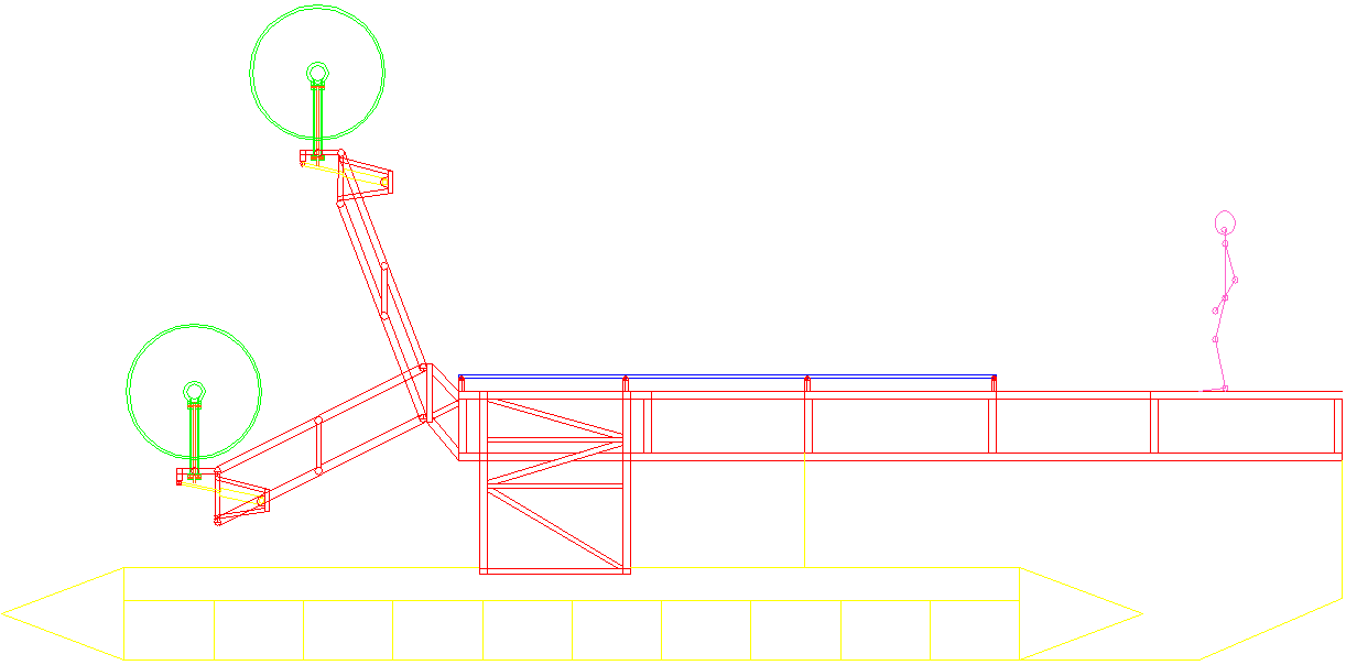
COASTAL CLEANER SIDE VIEW - This is a draft design for a coastal/river test rig based on the SeaVax concept. Unlike SeaVax, this low budget development boat will be built of steel, not aluminium, to keep the up front costs down, though long-term use would favour aluminium alloys. As to economics, who might pay for the operations of such a vessel locally remains to be answered. Unlike a dustcart that collects household waste, there is no immediately obvious health hazard from not cleaning the oceans, rather it is out of sight, toxic, cumulative and just as deadly. Copyright © diagrams March 2019. All rights reserved, Cleaner Ocean Foundation Ltd.
Youtube
LINKS & REFERENCE
http://en.wikipedia.org/wiki/Wind-powered_vehicle Massive-cargo-ship-will-harness-the-wind NedWind Rhenen bV NW 43/500 (Turbine), Nedwind website. 27 January 2013. Why 2-Blade?, GC China Turbine Corporation website. 27 January 2013. (WO1992012343) Wind Turbine, Patentscope website, 1992. Furling tail windturbines (page 18) PDF "Power from the Winds." Popular Mechanics, June 1954, pp. 124-125. Yavuz Ali Şener "Gelibolu Modeli" Ruzgar Turbinlerinde Verimlilik Parametrelerinin Arastirilmasi ("Gallipoli Model" Investigation of Wind Turbines Efficiency Parameters) Project No.: Misag-7, Ankara, 1995. (PDF images in Turkish) Ward, Logan. Windbelt, Cheap Generator Alternative, Set to Power Third World, Popular Mechanics October 1 2007 Sofge, Erik. Shawn Frayne Makes Another Leap in Wind Power: Breakthrough Winner Update 18-12-2009 Description of several types of wind turbines –including piezoelectric Power generation system utilizing wind draft from vehicular traffic Mark Oberholzer's roadside Darrieus wind turbine design BWEA website, (account required, scroll down to SPERBOY) Young, Kathryn (2007-08-03). Canada wind farms blow away turbine tourists Edmonton Journal "New US Rooftop Wind Turbine Lab". Renewable Energy World. 2009-07-07. Leake, Jonathan (2006-04-16) Home wind turbines dealt killer blow London: The Sunday Times http://gas2.org/2012/02/26/new-lng-viking-cruise-ship-cuts-emissions/ http://gas2.org/2012/01/31/nissan-builds-solar-diesel-ship-to-transport-eco-cars/ http://en.wikipedia.org/wiki/Lifting_body http://en.wikipedia.org/wiki/Apparent_wind Hydroptere-The-worlds-fastest-sailboat-hoping-sail-Pacific-record-time
Solar House, BN27 1RF, UK + 44 (0) 1323 831727
BRICKS & MORTAR - FILTRATION - GLASS & PAINT - GANTRY - HYDRODYNAMICS HISTORY - INSTRUMENTS - OUR TEST TANK - SEAVAX TEST VIDEOS - SLUICE GATE - WAVE MAKING - WIND MACHINE
|
|||
|
This page is Copyright © 2019 Bluebird Marine Systems Ltd. The names Bluebird™, Bluefish™, Miss Ocean™, SeaNet™, SeaVax™ and the blue bird & fish in flight logos are trademarks. All other trademarks are hereby acknowledged.
|
|||
