|
SEAVAX - TESTING TANK GANTRY DESIGN
BRICKS & MORTAR - CARRIAGE - DRAINAGE - FACILITIES - FILTRATION - GLASS & PAINT - GANTRY - GIMBALS - HATCHES - HYDRODYNAMICS HISTORY - INSTRUMENTS - LABORATORY - LAMINATING - LOGISTICS - OUR TEST TANK - PROOFING - REVIEWS - SCREEDING - SEAVAX TEST VIDEOS - SLUICE GATE - SOLAR BATTERIES - WAVE MAKING - WIND MACHINE
|
|||||||||
|
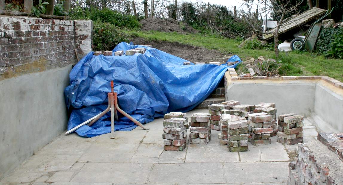
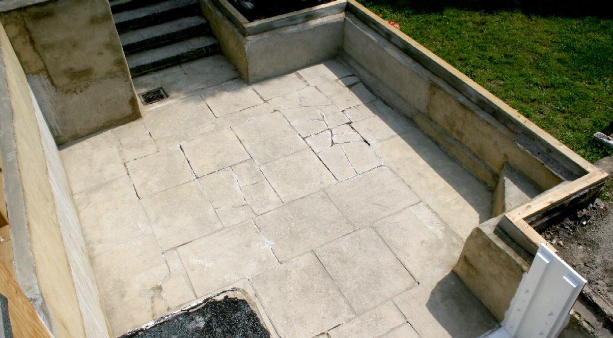
SITE CLEARING - This is an ideal location for a private test tank facility, seen here under construction by converting an old garden unit that can go back being a greenhouse or other storage unit. There are two convenient drains for emptying and steps to allow for easy launching of the SeaVax and other ship models. We can simply walk in with angling type waders, or roll up our trousers, where the water is warm thanks to solar heaters. As you can see, the brick walls have been rendered up to a height of about 750mm and a bit more.
Instrument package and gantry design is very important. We need to be able to adjust the floating height for various tank fill and wave or wind generated conditions. The unit must rotate to change between wave, wind and recirculating mode, with some leeway built in for precise location. Where the budget for the conversion of the former cottage base to a water tank is under £5,000, the instruments and mechanical support package will be somewhat more costly, but thanks to help from Avaaz and all those who contributed so generously, Phase I of this project is now supported.
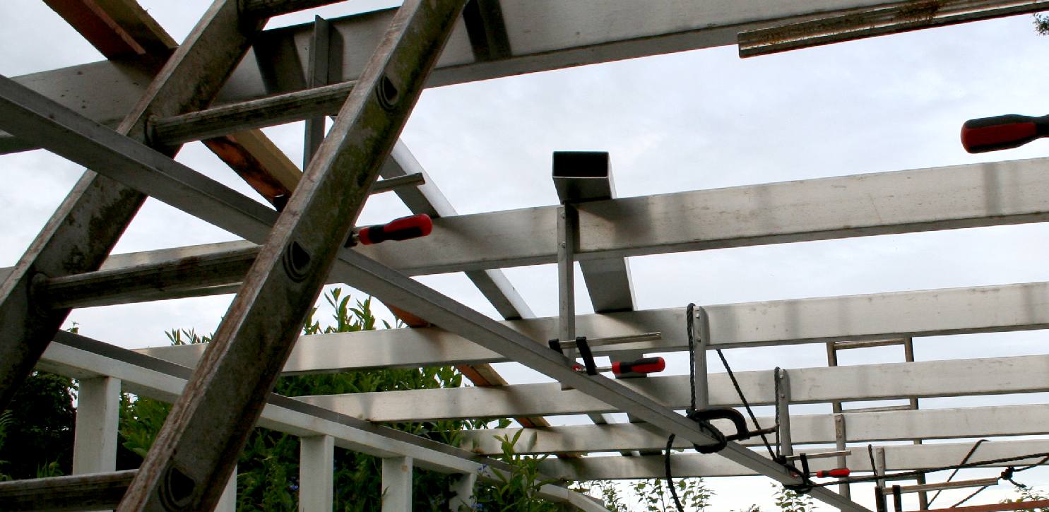
SIDE VIEW - This is a side view is of the overhead beams and stainless steel gantry. You can see the sluice gate in red on the left as a reference point. The gantry is of stainless steel "T" beam construction with four wheel bogies that supports a cross-beam, also of "T" section stainless steel. The tank has a fill height of 22 inches (560mm) for wave making operation to an overall height of 39" inches (996mm) for storm condition, and 27" inches (685mm) in recirculating mode. That is more than enough to test most boats in 1/20th scale and larger ships or submarines up to 400 feet in 1/40th scale. When the doors are closed the whole cubicle is water resistant - and a little leakage from serious storm simulations will not upset our engineers.
PLAN VIEW - This plan view is of the overhead beams that support a stainless steel gantry. You can also see the sluice gate in red on the left. In this design the gantry is a stainless steel "T" beam with four wheel bogies. This is a first draft CAD diagram showing a central gantry, since then (16-4-16) we have gone over to a gantry with two widely spaced "L" angle, or "T" beams. This design issue is with our engineers at the moment (25-4-16).
GANTRY REVISIONS - This is a much more solid design, allowing us to build in more features that are sure to be needed when conducting wind and wave tests. The twin rails overhang on either side of the tank for easy loading and to be able to make adjustments to the test rig, without the need to get wet (go wading), or drain the tank (26-4-16). In this diagram the SeaVax model is show west-east. For wave tests she will be facing north-south for hull speed length ratio evaluations and west-east for general stability testing.
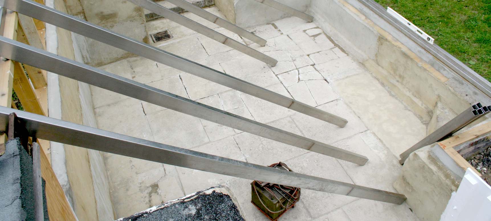
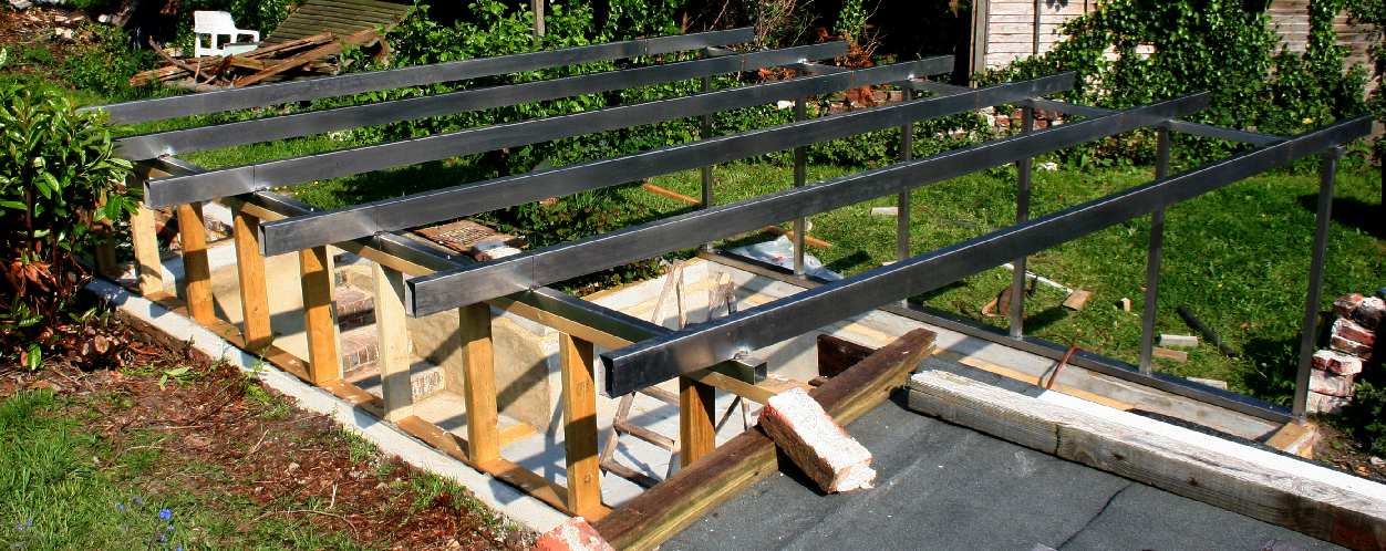
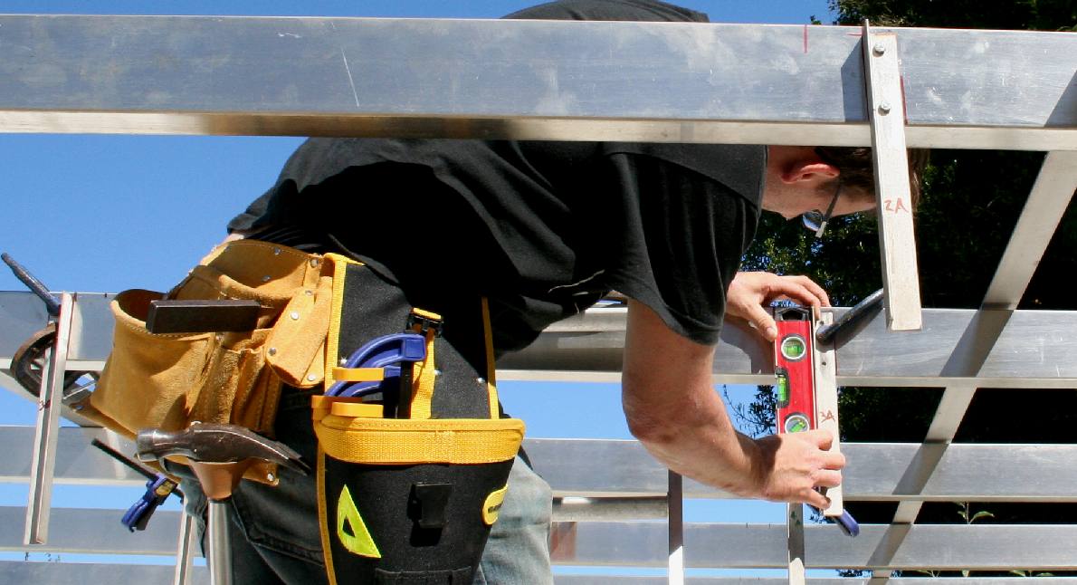
CONSTRUCTION - Putting up the stainless steel beams and uprights is a lot quicker than cutting the beams to size and fabrication. On site welding skills are the essential ingredient - that and a reliable tape measure and a spirit level.
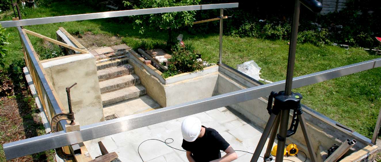
RECIRCULATING WAVE - In this position SeaVax can be tested for hull speed and other sea-keeping qualities using the twin-pump recirculating system. In order to be able to fit the metal guides to be able to use the tank for hydrodynamic drag testing, we had to remove some old cottage steps that were now redundant - first recording the archaeology.
BOGIE DETAILS - Here is the 1st draft for the bogie wheels that run inside on the lower ridge - and on the outside of the upright ridge of an "L"section angle in stainless steel. Our wheels are likely to be off-the-shelf nylon units, adjustable for clearance and sprung, to give a tight fit, but smooth action when loading the model onto the gantry and swinging into position, until locked for testing. The design needs to be as simple as possible so that we can build it quickly - and yet versatile enough for us to conduct a variety of tests.
LOADING - This is an example of how we might load the SeaVax model onto the gantry rails. The helipad tilts upwards, so will not foul the walls - and the whole boat may be positioned south-north further south on a sub-carriage that is part of the main mounting frame (not shown). In addition, the carriage rotates and may be locked in any position on the compass. Please note that these diagrams are Copyright © April 28 2016, Bluebird Marine Systems Ltd. You will need our permission to reproduce any of this/these series of pictures.
One thing that you may notice from the pictures of other test tank rigs on this page, is the huge variety of designs and the different methods used in tow and wave tank testing. It seems that every installation is a custom build with no industry standard, other than the liquid medium: water. Of course all of the hulls being tested are also custom designs. It is though a good idea to test some common hull designs to get a feel for what has been done before. We call this running a base line. In aerodynamics (aviation) the baseline would be a flat plate and a pure teardrop (1.28 to .045 Cd). In the marine world these basics do not apply, but in the automotive world, the shape of a car is one of the keys to more miles per gallon.
FLUID DRAG - An example diagram from NASA. The drag coefficient Cd is equal to the drag D divided by the quantity: density r times half the velocity V squared times the reference area A: Cd = D / (A * .5 * r * V^2) This formula may be modified to find pipe drag, or skin friction drag for submerged hulls (submarines). Skin friction drag needs to be added to wave drag (and air drag from the superstructure) to give the total drag on the hull. The air drag quotient may not be in the same direction as the hull drag, hence, may be a vector to advantage transit, or a nuisance, depending on where and how the SeaVax unit is deployed.
BERGEN - In this Edinburgh design, side mounted twin rails are used to carry the tow tank carriage. Typically, there is quite a bit of spaghetti on a carriage.
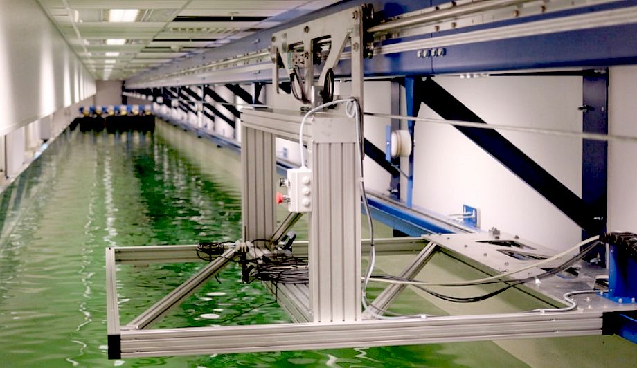
STADT - Twin hulls mounted on aluminium sections on an overhead gantry that looks a great deal simpler than other rigs. The longer a tow tank, the longer the electrical harness, unless wireless transmission technology is used.
MASTHEAD - The instruments used on this test tank roll on two metal wheels running above tracks alongside the tow tank. It looks a bit delicate, but is sure to work.
SPEED LENGTH RATIO (SLR)
One of the most common uses for a water basin, or tow tank, is to establish the "Hull Speed" or "Displacement Speed" of a particular hull design. As the length of a ship increases this may not be so important as entry and exit angles, but for smaller ships and boats, the designer needs to know the hull speed, or rather the hull length and shape needed to perform a particular function efficiently. Fluid dynamics is therefore important, as is the configuration of a multi-hull arrangement - that tends to complicate matters.
Wave making resistance depends on the general proportions and shape of the hull: many modern displacement designs can easily exceed their 'hull speed' without planing. These include hulls with very fine ends, long hulls with relatively narrow beam and wave-piercing designs. Such hull forms are commonly achieved in competitive rowing boats, catamaran fast ferries and SWASH designs.
'Hull Speed' is the speed at which the wavelength a boat's bow wave (in displacement mode) is equal to the boat length. As boat speed increases from rest, the wavelength of the bow wave increases, and usually its crest to trough dimension (height) increases as well. When hull speed is reached, a boat in pure displacement mode will appear trapped in a trough behind its very large bow wave.
The concept of hull speed is not used in modern naval architecture, where considerations of the SLR or Froude number are considered more helpful. William Froude (28 November 1810 in Devon – 4 May 1879 in Simonstown, South Africa) was an English engineer, hydrodynamicist and naval architect. He was the first to formulate reliable laws for the resistance that water offers to ships (such as the hull speed equation) and for predicting their stability.
In the case of workhorse like SeaVax, this may not be so important. Our boat is not designed to traverse the oceans at high speed or to use the least amount of fuel for a journey. Our boat needs to be able to cope with prevailing conditions while it filters seawater. Getting from point A on the planet to point B is less important, though of course a necessary function. We need to achieve a stable working platform as the prime consideration. In this regard, the challenges are similar to designing an oil rig, except that an oil rig has four legs and no wind turbines to work into the equation.
SOUTHAMPTON - Here a substantial bridge gantry moves across the tow tank on steel wheels rolling on metal tracks on either side of the water basin. This is not a very energy efficient design, using a lot of steel. You can see two technicians on the bridge with a laptop.
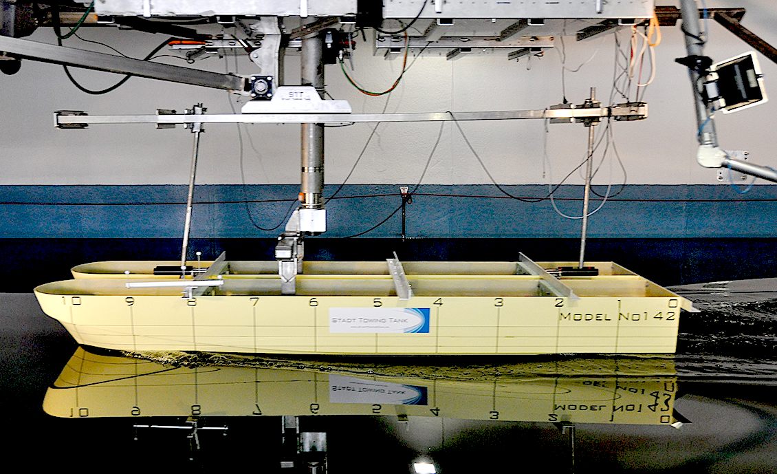
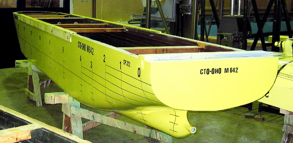
SIDE VIEW - A nice example of how a model ship hull is marked for observation and filming during tank testing. Ostsee, Gdansk, Poland.
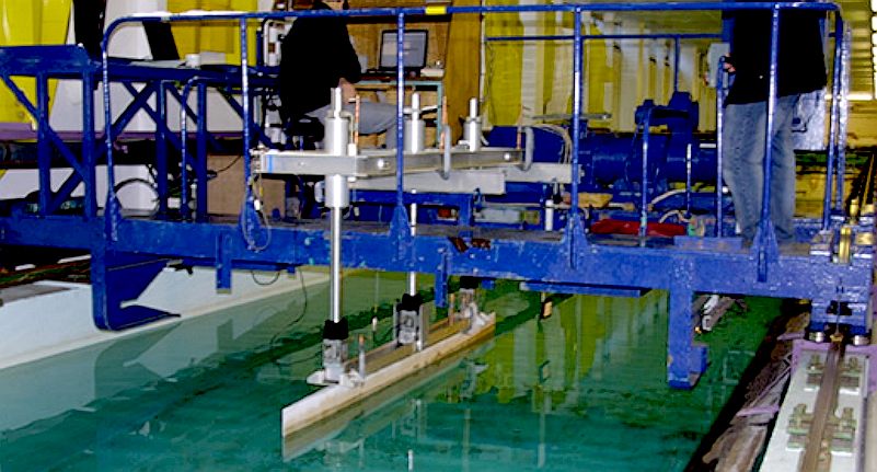
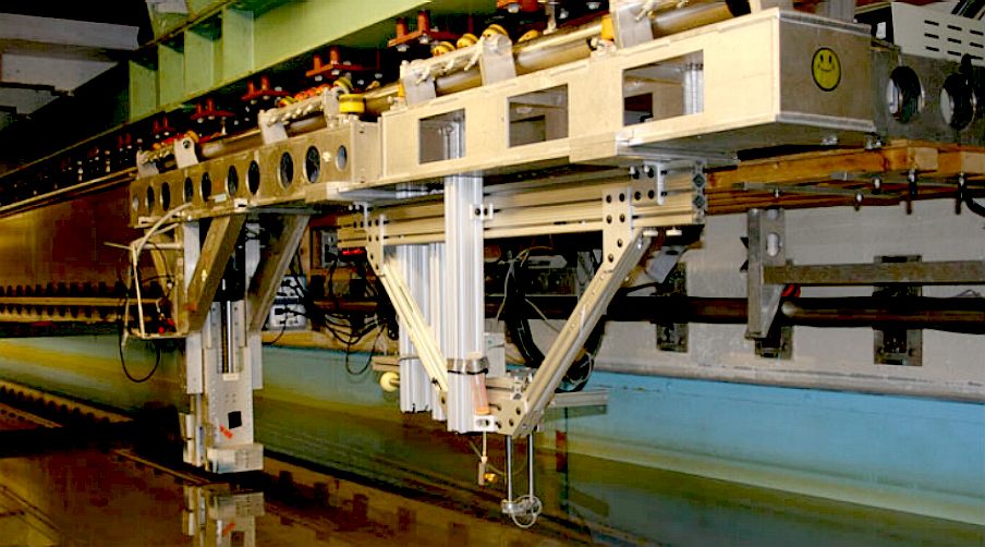
HEAVY DUTY - This test rig looks seriously solid, with yellow rollers running over the top of what looks like a stainless steel tube. The are a lot of adjustable anodized aluminium sections hung underneath.
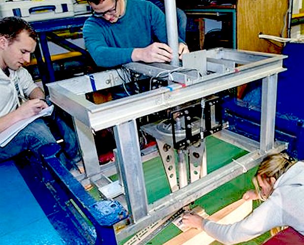
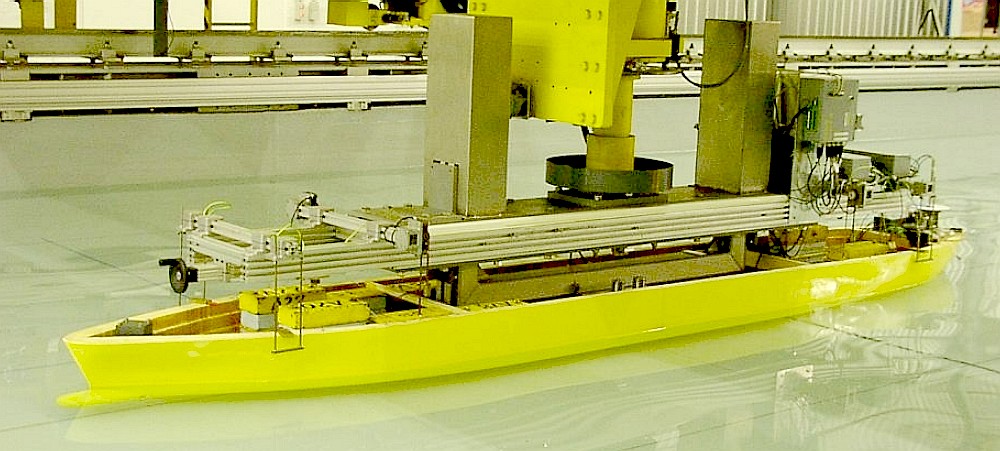
NEAT - Wow! Full marks for design integration. Here, the carriage is so loaded with measuring equipment, it is bigger than the vessel.
WIRING HARNESS - MARINTEK, The marine research institute in Norway has a fabulous tank to be able to test quite large ships for more than just hull evaluation. They appear not to be that bothered about overhead wiring issues. Nice model!
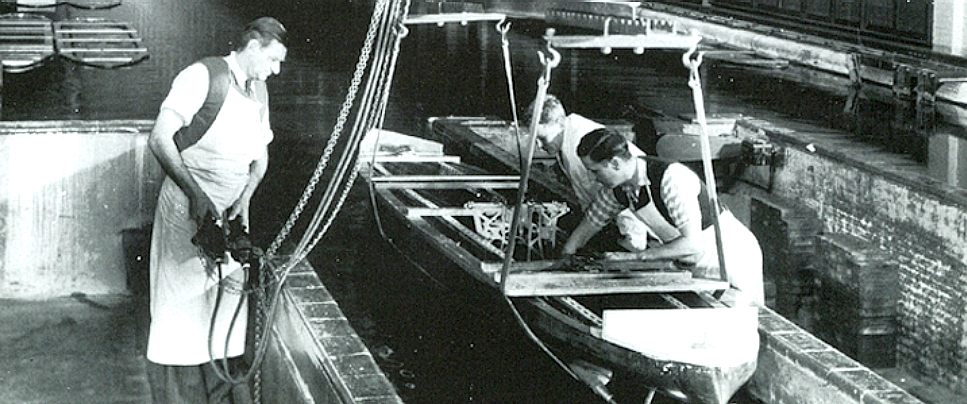
NATIONAL PHYSICAL LABORATORY - A picture from the archives, a large model ship is readied for launch in their test tank. The NPL opened its first ship tank on 5 July 1911. It was 150 m x 9 m wide and held 5000 tonnes of water with a centre depth of 3.75 m. A marine engineer and shipbuilder, Alfred Yarrow, provided £20,000 for the tank's construction to enable the testing of ship models. It was originally known as 'The National Experimental Tank'; later the 'William Froude National Tank' after the famous engineer and naval architect. We love the powered (twin) hoists with straps on the underside of the model ship hull, for lowering into the water. Our system can be operated by one person, but then our model is smaller.
UNPAINTED - Rebuilt and rendered walls, renewed timbers and a sluice gate. Now all this water basin needs is a coat of paint and a roof. Please note that this photograph is Copyright © May 28 2016, Bluebird Marine Systems Ltd. You will need our permission to reproduce this photograph, except for private or educational use.
WELDING - We have our own fabrication facilities, though we are limited in size, save for where the great outdoors is not a problem. Our beams needed some adjustment, that warranted MIG welding, before we could install them over the test tank. The Youtube video above shows how we turn a job like this into a very short production run. Please note that this video is Copyright © June 2016, Bluebird Marine Systems Ltd. You will need our permission to reproduce this short film, except for private review or educational use.
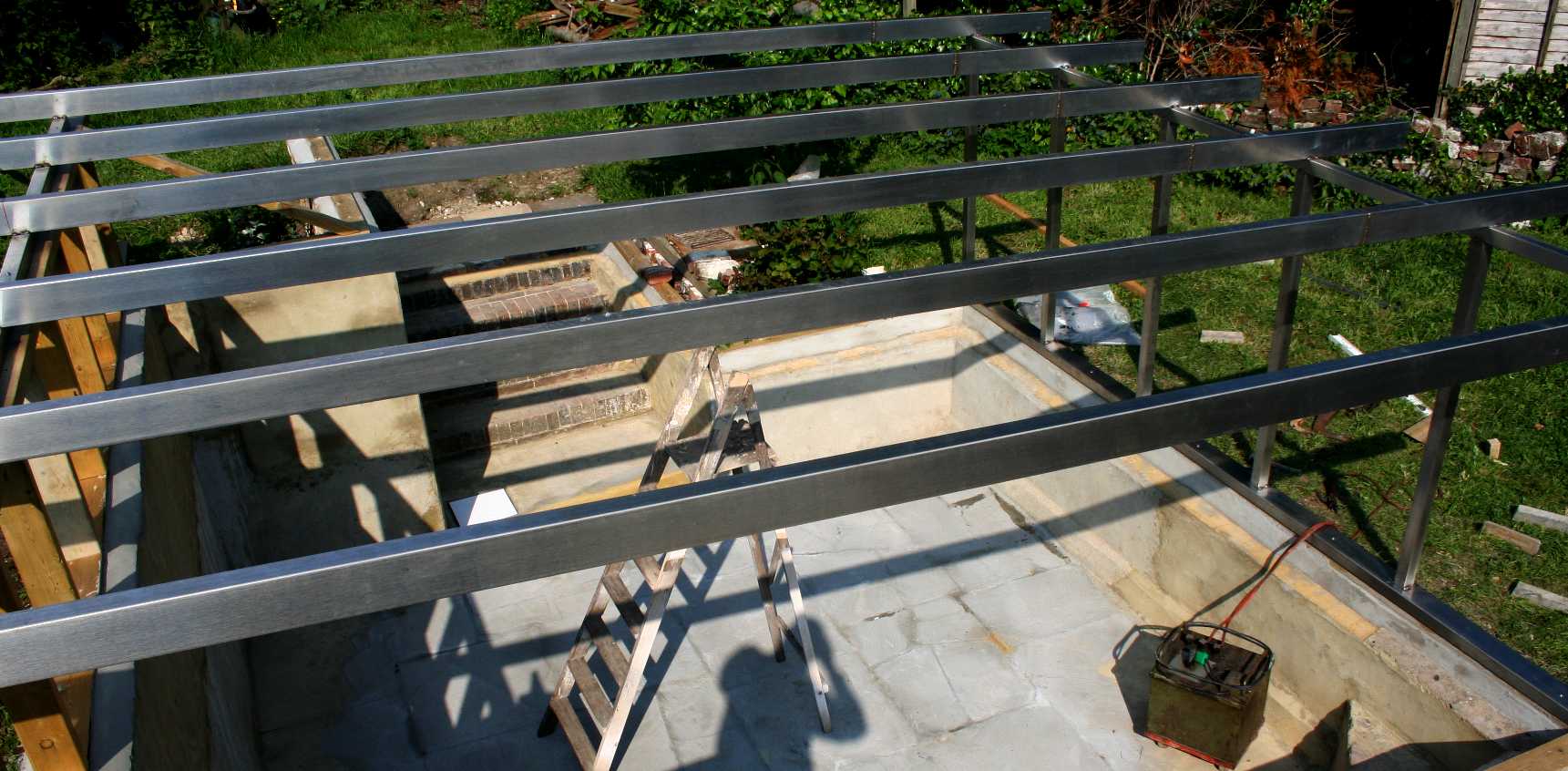
STAINLESS BEAMS - The stainless overhead support beams and the uprights are now cut to size, welded, and ready to be installed. For this part of the operation we are using a legacy Oxford Bantam stick (arc) welder with dissimilar (high nickel content) metal electrodes to tack and weld the frame in situ - which assembly is then bolted to the timber wall plates. Stick welding is usual in windy locations, where the shielding gas used in a MIG welder would be blown away - and so yield an inferior weld - without wind breaks. Traditionally, ship yards used stick welders, but the skill level needed is very high. For SeaVax and AmphiMax, we'll be using the finest spool-on-gun welding machines to speed up production and ensure quality welds. Not because we don't have the in-house skills, but simply to advantage our crew of the latest advances in technology. Please note that this photograph is Copyright © June 2 2016, Bluebird Marine Systems Ltd. You will need our permission to reproduce this photograph, except for private or educational use.
HEY HO AND UP SHE RISES - Two stainless-steel beams are drilled and bolted to the timber wall plates. From there two of the gantry/roof support beams are clamped into position ready to be tack welded in place. Readers might like to know that Joseph Cyril Bamford CBE (21 June 1916 – 1 March 2001), the founder of the JCB heavy plant manufacturing company began his business with the purchase of an English Electric arc welder for £1 in 1945. Please note that this photograph is Copyright © June 5 2016, Bluebird Marine Systems Ltd. You will need our permission to reproduce this photograph, except for private or educational use.
ON THE LEVEL - The gantry support beam positions are measured to the half-millimeter. Unfortunately, the old building is not quite so accurate, so we have to make adjustments (fettling) to be sure that each beam is 30.5" inches (775mm) apart from its neighbor. Once marked, the remaining beams can be clamped into position for welding. Please note that this photograph is Copyright © June 5 2016, Bluebird Marine Systems Ltd. You will need our permission to reproduce this photograph, except for private or educational use.
JIGGED - Once the fitting up is completed the job is almost done. Painting of the test tank is next, followed by the gantry rails and the roof. We'll be afloat in no time now - with a test fill up. We must though fit a filtration system after that, or in not very long the tank will go green and turn into a pond. Please note that this photograph is Copyright © June 5 2016, Bluebird Marine Systems Ltd. You will need our permission to reproduce this photograph, except for private or educational use.
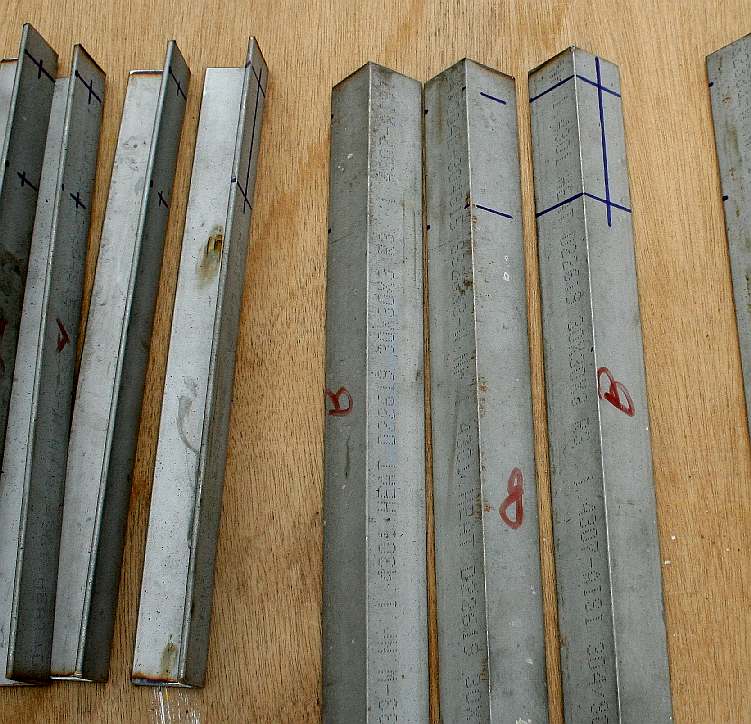
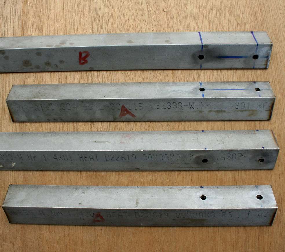
SUPPORTS - The gantry rails are suspended from the main roof beams by 14 stainless steel angle section uprights of unequal length, seen here as 'A' and 'B' struts. They were batch drilled in our workshops and then cleaned ready to be fitted.
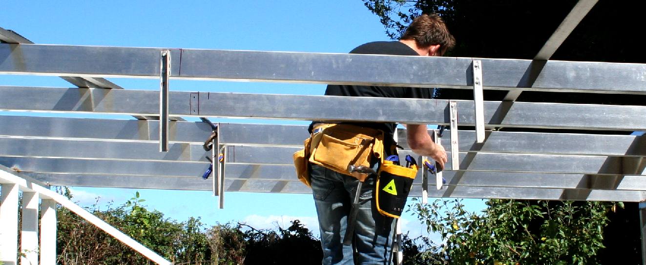
CARRIAGE - The support beams were marked out and the uprights are fitted to the stainless steel roof beams. Chris is seen here jigging up the sections and clamping in position.
LEVEL - Each upright is checked to make sure they are within tolerances. They need to be vertical so that when the carriage 'L' section rails are welded in place, that the whole assembly will run horizontally with minimal effort on the part of the scientists conducting our research. Copyright © September 12 2016, Bluebird Marine Systems Ltd. You will need our permission to reproduce these photographs, except for private or educational use.
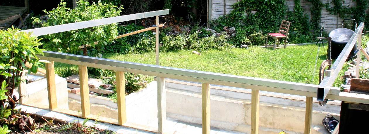
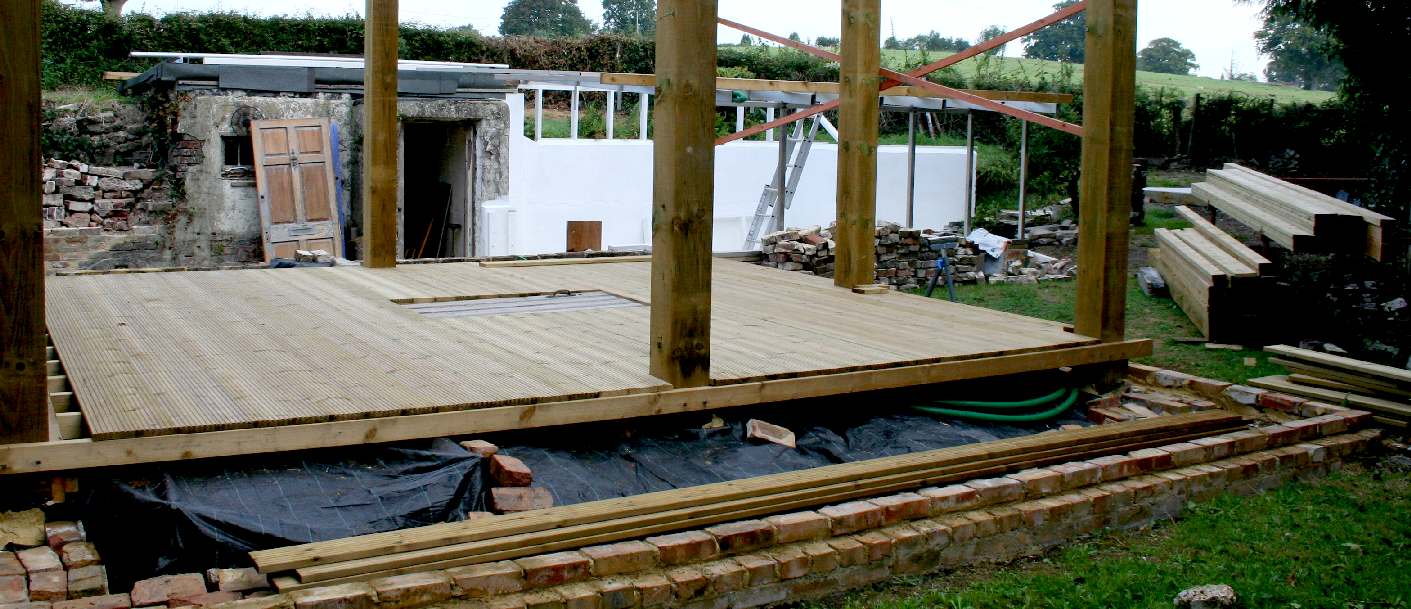
OBSERVATION PLATFORM - What was once a pile of rubble and dangerous to walk around, is now taking shape as our observation platform - and is now safer for the occasional visitor. The hatch in the middle of the decking is temporary, until we have more of the test tank operational. You can see the test tank in the background in this picture. Copyright © September 12 2016, Bluebird Marine Systems Ltd. You will need our permission to reproduce these photographs, except for private or educational use.
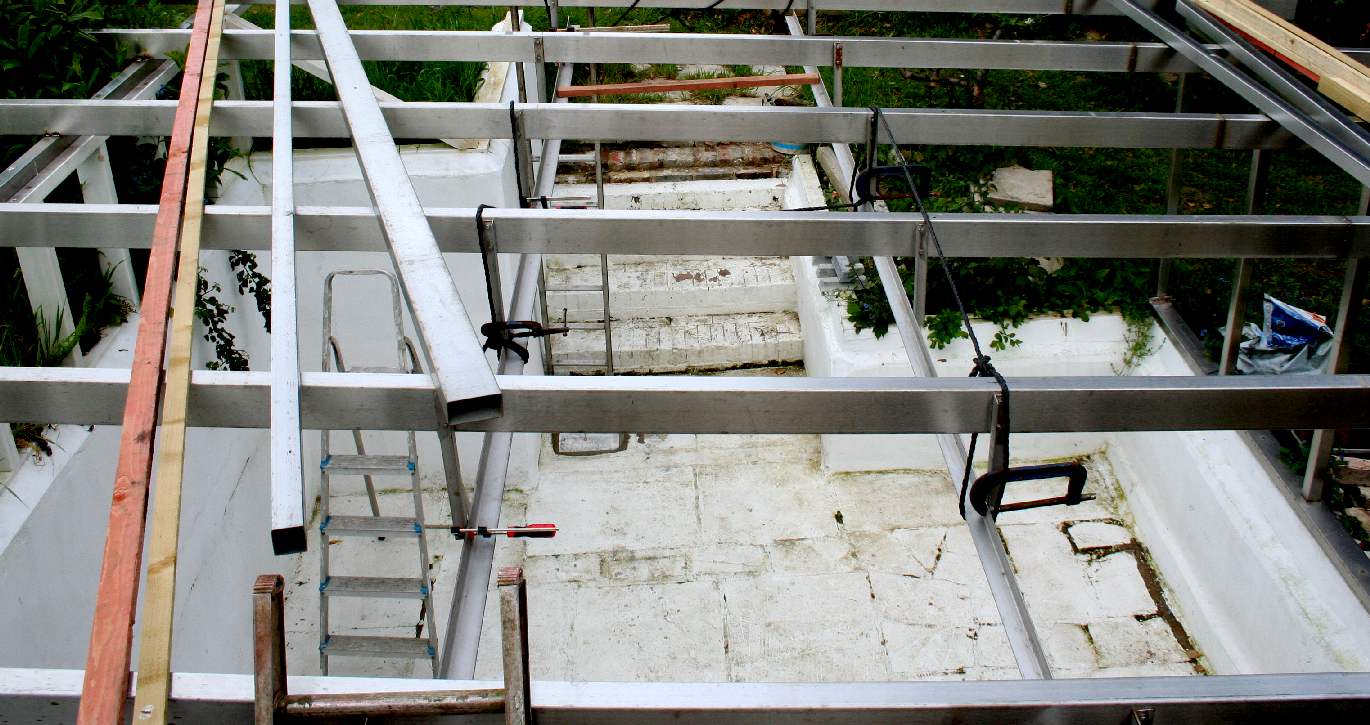
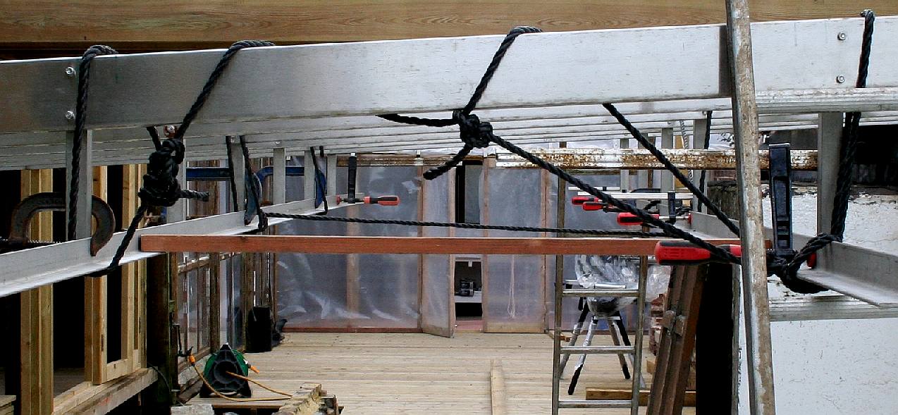
CLAMPED - Seen here clamped in position, the rails will be welded to the uprights, while the uprights are bolted to the gantry frames. This system allows us to change (modify) the tracks relatively easily, compared to cutting welds - if the whole unit had been constructed as a welded unit. Copyright © Bluebird Marine Systems Ltd. You will need the permission of BMSL to reproduce these photographs, except for private or educational use.
SCREED - Having operated the tank several times last summer and autumn, we found that it leaked and that the rate of leakage was increasing. We put up with these leaks for the basic tests we needed to do to be sure the SeaVax concept worked. But after that we decided that it would be prudent to screed the floor and repaint the tank in epoxy paint, rather that the masonry paint used last time. In this picture you see the tank after a period of rough use and a winter. Unfortunately, the underground tank also developed a leak that we could not stem sufficiently to continue using as it is/was. We are arranging for the holding tank to be lined with GRP to eliminate this problem. The good news is that our cleaning pumps and vacuum work rather well. We also have a petrol powered blower to dry the tanks in between servicing operations. Copyright © Bluebird Marine Systems Ltd. You will need the permission of BMSL to reproduce these photographs, except for private or educational use.
CARRIAGE MODS - Here you can see that we are making improvements to the overhead tracks that are used to roll the carriage that carries the SeaVax model into position for testing purposes. It is important to that each track is level with the other, given that the gantry frames are installed at an angle. Note that we now have a solid floor in between the robot lab and the water test tank. Our volunteers continue to work on the facilities in the hope that additional funding can be secured for 2017 into 2018. Fund raising is now the responsibility of the Cleaner Oceans Foundation, with BMSL volunteers providing technical support on a not for profit basis. Copyright © Bluebird Marine Systems Ltd. You will need the permission of BMSL to reproduce these photographs, except for private or educational use.
LINKS & REFERENCE
https://avaaz.org/ https://www.grc.nasa.gov/www/k-12/airplane/shaped.html https://www.uni-due.de/IST/ismt_circulation_tank.shtml http://www.edesign.co.uk/portfolio/plymouth/ https://www.plymouth.ac.uk/research/institutes/marine-institute/coast-laboratory http://www.building.co.uk/making-waves-plymouth-marine-laboratory/5069697.article info@marin.nl http://www.marin.nl/ https://en.wikipedia.org/wiki/Maritime_Research_Institute_Netherlands http://www.designindaba.com/articles/creative-work/award-winning-ocean-cleanup-team-launch-their-first-open-water-test http://www.bbc.co.uk/news/uk-england-35909651 http://stamco.co.uk/
BRICKS & MORTAR - FILTRATION - GLASS & PAINT - GANTRY - HYDRODYNAMICS HISTORY - INSTRUMENTS - OUR TEST TANK - SEAVAX TEST VIDEOS - SLUICE GATE - WAVE MAKING - WIND MACHINE
|
|||||||||
|
This page is Copyright © 2018 Bluebird Marine Systems Ltd. The names Bluebird™, Bluefish™, Miss Ocean™, RiverVax™, SeaNet, SeaVax™, and the blue bird & fish in flight logos are trademarks. All other trademarks are hereby acknowledged.
|