|
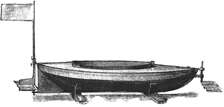
Herman Linden's 'Autonaut' Naples, 1895
The
destructive power of a wave crashing on a beach has fascinated mankind for
thousands of years. Imagine capturing that huge force of nature to propel a
ship. In Naples,
Italy, in 1895 Herman Linden noticed that a wave passing by a boat caused the
boat to rise and fall. He thought to use that phenomenon to power a vessel and
to prove his theory, he built his 'Autonaut' seen above. The
tantalizing dream of free propulsion without sails
has galvanized hundreds of inventors
to action. Some of which are mentioned below. A foil system is basically the
reverse of a fishes fin. Where a fish (or mammal) moves its tail fin to-and-fro
to generate propulsive force backwards, the fish moves forward. Now
imagine the fish remaining still (on its side) just below the water surface, and
a wave wafting over its tailfin. The fin will move up and then down in harmony
with the oscillating motion of the wave - the result of which will be to push
the fish
forward involuntarily without any muscular effort. A fish is not a good example
because its tailfin is vertical, but a whale, whose fin is horizontal - and is a
much larger animal, will benefit from wave motion as an aid to propulsion. See
research from 1989 below. The
question is, how fast can a boat or ship go using foils to replicate this
phenomenon? Without any practical knowledge on the subject, it seems that
a large ship will be unable to generate sufficient propulsion from wave energy
alone to attain practical sailing speeds. This is because the larger a ship
is, the smaller are waves in proportion to hull size. Thus, the technology
appears not to be scalable (in practical terms). It is though a fascinating
research subject. A bit like the perpetual motion puzzles that baffle
laypersons.
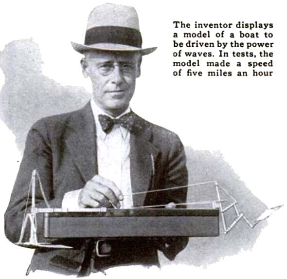
Unknown inventor from Long Beach, CA, shows off his 18" prototype in 1935
WAVE POWER - POPULAR SCIENCE APRIL 1935
Popular Science claims that it remained for an inventor of Long Beach, California, whose name is not mentioned, to design a wave-operated mechanism to propel a boat (Popular Science, 1935), see
picture below. Two fins in the bow and one fin in the stern attached to flexible joints provided the propulsion. The 18-inch model built by the inventor could reportedly attain a pace of five miles per hour, with its relatively large fins compared to the waterplane area of the
hull. POPULAR SCIENCE 1950 - 1975
In the latter half of the 20th century, more stories about people that had built
wave-powered boats appeared.
These includes John S. McCubbin of Victoria, Australia (Popular Science,
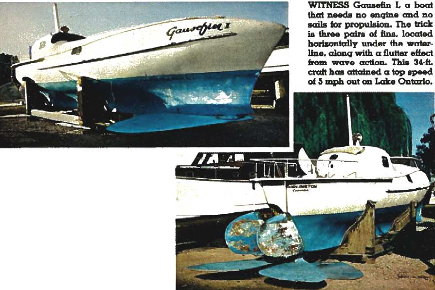
1950), and Joseph A. Gause (Mechanix Illustrated, 1972) of Burlington, Ontario, Canada.
Gause filed his first
patent for a wave-powered boat in 1966. Gause’s 34 ft boat, Gausefin I, attained a top speed of 5 mph on Lake Ontario, using wave energy only, witnessed by five Canadian Government officials who were cruising alongside.
Gausefin I had three pairs of fixed fins rigidly attached to the hull. The fins were thickest at the root and gradually tapered outward toward a thin trailing edge allowing for the fins to flex when hit by a wave. According to the Mechanix
article, the size, angle, thickness and flexibility of the fins were arrived at
through guesstimating.” Gause, a sculptor and painter, certainly knew the historical background of wave-powered boats, as he cites both Vrooman and the Popular Science article of 1950 in one of his four
patents (Gause,
1967).
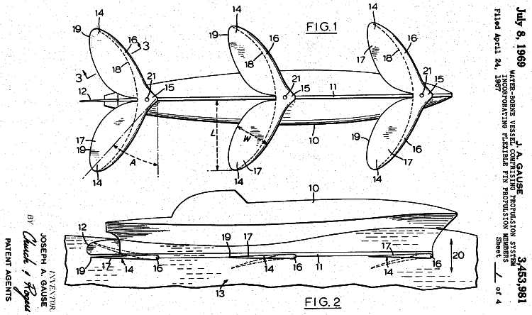
US
Patent drawings J A Gause 1969, No: 3,453,981
EINAR JAKOBSEN "NORGE RUNDT" NRK AND OTHERS 1983 - 2010
In 1983 Einar Jacobsen experimented using combinations of two and four foils.
These foils had an area of 500mm2 and were used on a sailing boat
hull-form that was 7.5 meters long. With this configuration Jakobsen recorded a
top speed of 6 knots on one occasion. Soon after that Mr Jakobsen was granted
the sum of NOL 450,000 by the Norwegian
Government, such as to be able to conduct research on the Kystfangst, a 20 meter
long fishing vessel, that was at the time owned by the Institute of Fishery
Technology Research. The
Kystfangst had a bulbous bow as a means to induce laminar flow. On each side of
the bow was a foil in similar fashion to the experiments on the small sailing
boat. According to a website belonging to Eirik Bøckmann,
in a sea state with waves of some 3 meters, the twin foils provided a propulsive
force as a function of percentage (15-20%) of the boats total resistance (Ref.
Berg, 1985). The Kysfangst managed a velocity of between 4-8 knots, with the
benefit of reduced pitching in head seas, and a reduction in roll. Model
tests conducted between 1979-2010 (Kjærland, 1979; Nagata et
al. 2010) suggest that the highest speeds for wave assisted ships are when the
wave length is about 1 to 1.5 x the vessels length, in both beam and following
seas. And, 1.5 to 2.2 x a vessels length in head on seas. Where the Kystfangst's
trials were in seas with wave-lengths of 80 meters (4 x the ships length) and
wave periods of 7 to 7.5 seconds, the results confirmed that the longer a ship
the greater the benefit. See the WAFT project below. At
the same time that Jakobsen was experimenting, Hiroshi Isshiki had begun a
conceptual study of wave powered boats in Osaka, Japan (Isshiki,
1982; Isshiki & Murakami, 1983-84). Mr Isshiki worked for the Technical
Research Institute at the Hitachi Shipbuilding Company. There was some
controversy over use of, and who first coined the phrase: "wave devouring
propulsion," attributed to Professor T Y Wu of the California Institute
of Technology in 1980. There is though no IP protection for a phrase, save for a
trademark. In
parallel with these efforts, in 1982 Yukata Terao of
the Tokai University in Japan was also working on "wave devouring
propulsion." Then in 1991 Terao (Terao & Isshiki, 1991) published
his results from full scale testing of a 15.7 meter long fishing vessel with a
hydrofoil area of 7.4% of the ships waterline area. From these results it should
be possible to find the best ratio of foil area to hull length - though it seems
logical to assume that if the foil is bigger (area) then the potential thrust must be
greater, provided that the ship is of sufficient mass to provide a beneficial
fulcrum and that the foils are not so large as to suffer drag penalty. Once again, in these tests there was reduced pitching (bow slamming) in
head seas and a reduction in roll. If there had been no waves, the extra drag
would reduce speed, but with larger waves there is an increase of ship speed. 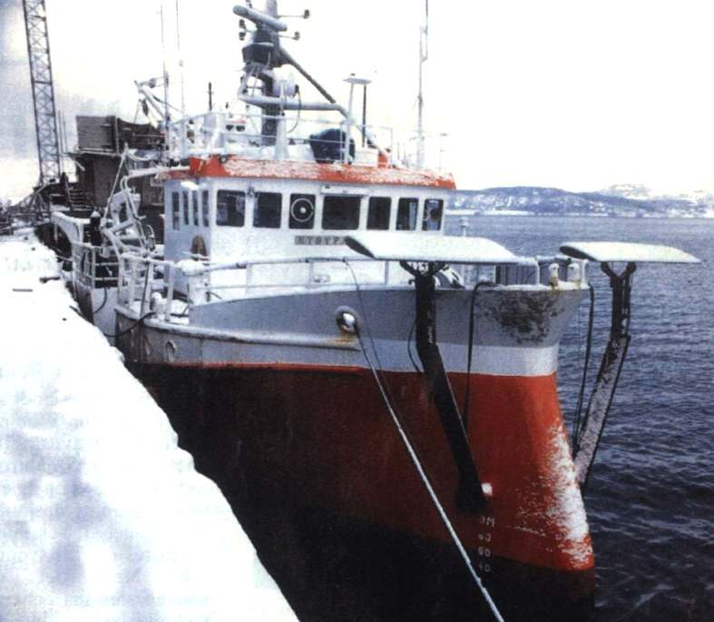
The
Kystfangst, Norwegian fishery vessel - with foils in raised position
WHALE OF A TAIL
Reasearch by N. Bose and J. Lien at the Memorial University of Newfoundland in 1989, found that the flukes of
cetaceans are capable of absorbing energy from ocean waves for propulsion. The extent of this energy absorption is demonstrated by considering the flukes of an immature fin whale (Balaenoptera physalus). In a fully developed seaway corresponding to a wind speed of 20 knots (around Beaufort force 5) and at a low swimming speed, of 2.5 m s-1, this whale was able to absorb up to 25% of its required propulsive power in head seas and 33% of propulsive power in following seas.
See O-Foil below. SHIPBOARD SAFETY
Potentially, waves contain 10 times more energy than the wind.
Calculations indicate that the use of active hydrofoil-propellers can generate economic propulsion for ships
and boats.
A propulsion system which its designer says will save more fuel than all other energy saving measures has been proposed by Wave Control CO
offering impressive efficiency.
It is claimed that such a system can extract power from passing waves (passive
foils), and that a powered version (active foils) can be constructed with an efficiency in
the region of 90%. This has also been confirmed by Veritec Marine Technology Consultants and professor J Lunde, at the University of Chalmers,
where they are quoted as stating that if the hydrofoil propeller is driven (upwards and downwards) by a motor the efficiency should be
90% - after the tail fins of our Dolphin
cousins.
Hydrofoils, usually horizontal, are supported by one or more struts and positioned below the water surface. They are pivoted, but are restrained or have attitude controlled precisely by mechanical, hydraulic or pneumatic spring systems or linkages.
Horizontal hydrofoils mounted below a hull are said to be not only more efficient than screw propellers but also to be able to use energy in the waves for propulsion. Hydrofoil wings have also a dampening effect on ships roll and pitch motions. 
The
Russian trawler Nikolaev in 1995, showing off its bow fins
Analysis of a foil propeller as an auxiliary propulsion system resulted in extraordinary efficiency for a vessel of 70 m length and indicated fuel savings in the order of
9 - 42% at vessel velocities of 9 - 15 knots. Some calculations were also performed for a vessel of 180 m length using data from the North Atlantic.
Extensive tests have been carried out with the 20 meter research vessel “Kystfangst” (180 GRT) equipped with two hydrofoils forward of the bow and slightly deeper than the keel.
In a seastate of about 3 m wave height, the foils produced a propulsive force corresponding to 15-20 % of the vessel’s total resistance (Berg, 1985).
Calculations carried out at the Veritec´s department indicates that a 50,000 ton
vessel with an over all length of 180 meters, navigating on the average wave
height in the North Sea, will be able to reduce the engine power by up to 61 percent at a speed of 17 knots.
SSI has together with Wave Control Co carried out tests in their test tank with a model of a catamaran (semisubmersible) from SSI using two, three and four horizontal hydrofoils attached at the side of the vessels bow or stern.
Mono hulls were also tested.
Two foils were positioned either at the side of the bows or complemented with one or two foils aft.
The tank's dimensions were 12 x 6 meter equipped with a wave generator. The test model was
built to 1:48 scale corresponding to a vessel of 60 m length. When the waves met the vessel it started immediately to advance and increased speed against the wave motions.
The foils were 19.0 x 4.9 cm to a speed of 7 m/sec. The wave height was 8 cm. wave length 2.07
meter. Corresponding to wave period of 1.15 sec and a wave length of 2.64 met, T= 1.3 sec.
It is found that up to 67% of the incoming wave energy may be converted to
propulsive force.
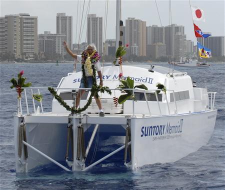
The
Suntory Mermaid II with Kenichi Horie waving at he bows
MARCH 22 2008 SUNTORY MAID & KENICHI HORIE
In 2008, Japanese sailor and environmentalist Kenichi Horie sailed the wave-powered catamaran Suntory Mermaid
II from Honolulu, Hawaii, to the Kii Channel, Japan (Geoghegan, 2008). The boat’s propulsion system was designed by Yukata Terao. The journey took 110 days, which was longer than planned, due to unusually good weather and calm seas. The journey is to date the longest known voyage by a wave-powered boat. The Suntory Mermaid II was widely, yet wrongly, described on the Internet as "The world’s first wave-powered boat".
This month, 69-year-old Japanese sailor Ken-ichi Horie will attempt to captain the world's most advanced wave-powered boat 4,350 miles from Hawaii to Japan. If all goes as planned, he'll set the first
Guinness world record for the longest distance traveled by a wave-powered boat and, along the way, show off the greenest nautical propulsion system since the sail.
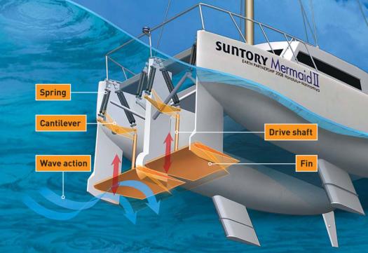
At the heart of the record-setting bid is the Suntory Mermaid II, a three-ton catamaran made of recycled aluminum alloy that turns wave energy into thrust. Two fins mounted side by side beneath the bow move up and down with the incoming waves and generate
dolphin
- like kicks that propel the boat forward. "Waves are a negative factor for a ship
- they slow it down," says Yutaka Terao, an engineering professor at Tokai University in Japan who designed the boat's propulsion system. "But the Suntory can transform wave energy into propulsive power regardless of where the wave comes from."
Horie's latest adventure builds on a storied career of eco-sailing. In 1993 he pedaled a boat 4,660 miles, from Hawaii to Okinawa, setting a world record for the longest distance traveled by a pedal-powered boat.
In 1996 he set the world record for the fastest crossing of the Pacific Ocean in a solar-powered boat. And in 1999, he made a solo trip across the Pacific in a catamaran made from recycled beer barrels.
With a maximum speed of five knots, the Suntory will take two to three months to complete a voyage that
diesel-powered craft accomplish in just one. But speed is not the point. The voyage aims to prove that wave propulsion can work under real-world conditions, opening up the technology for commercial applications such as cargo shipping. "Oil is a limited power source," Horie says, "but there is no limit to waves."
FORBES JUNE 2008 - WAVE RIDER
Waves can be used for a lot more than surfing. The Suntory Mermaid II is a 10-meter (33-foot) catamaran (a type of two-hulled boat) currently slowly propelling itself across the North Pacific solely using wave power. The boat is captained by Kenichi Horie, a 70-year-old Japanese marine adventurer who is attempting to sail it over 4,400 miles from Hawaii to Japan. The Mermaid is the first wave-powered boat ever to set sail, and Horie hopes to arrive in
Japan in the next few weeks after about 14 weeks at sea.
Wave propulsion systems are still in the early stages of development, but there is enormous potential for them to one day be used as an alternative energy source for much larger ships. A typical container ship–the sort that carries everything from automobiles to bottled “Fuji” water across the world’s oceans–burns up about 270 tons of fuel per day. That translates to over 100,000 tons of fuel in a year, or about $50 million per ship. If wave propulsion could even make a dent in that fuel bill, the savings would be huge.
The eco-friendly system propelling the Mermaid is the oddly named “Wave Devouring Propulsor System” (WDPS) built by Dr. Yutaka Terao, an engineer at Japan’s Tokai University. The system is essentially an underwater hydrofoil with two fins placed under the bow of the boat. Similar to the physics of an airplane wing, the waves generate low pressure on top of the fins and high pressure on the bottom. The pressure differential creates a lift in the fins, changing the direction up or down according to the angle of the flow acting on the hydrofoil, which in turn generates a thrust that pushes the boat forward. “The motion is very much like a dolphin kick,” explains Terao.
The hope, of course, is to eventually develop a wave-powered propulsion system that can be used on a commercial scale. But there are some major challenges.
“A ship set on a North Pacific Ocean course with an 80-meter hull could save 50% of its propulsion energy using the WDPS,” Terao says.
Speed is one of them. “Speed is very important in shipping,” says Olaf Mager, a spokesman for Germanischer Lloyd, a Hamburg-based transportation research company. And the Mermaid’s speed is too slow. While the average container ship today sails at speeds from about 15 to 25 knots (about 17-28 mph) the Mermaid can only manage 3-4 knots (about 4 mph).
Another challenge of the WDPS is managing the boat-to-wave-size ratio. For maximum efficiency in the water, the hull of a boat should ideally be a certain length in relation to the size of the waves it is sailing. Terao admits the Mermaid’s hull is too small for its wave conditions. “The Mermaid is about 10 meters” he explains, “and a more effective hull on the [Northern Pacific] waves would be 15 or 20 meters.”
But even for longer ships, the potential savings could be enormous. “A ship set on a North Pacific Ocean course with an 80-meter hull could save 50% of its propulsion energy using the WDPS,” Terao claims. But such a ship would still be less than one-third as long as so-called “Panamax” container ships–named because their dimensions are the largest allowed by the Panama Canal–which measure nearly 300 meters.
All these factors contribute to doubt that wave power is the future of shipping. However, the concept of the WDPS is so new that it hasn’t been studied thoroughly. Dr. Paul Sclavounos, a professor of mechanical engineering and naval architecture at the Massachusetts Institute of Technology, agrees the concept is interesting, but he’s not sure it could be used on ships larger than the Mermaid. “I can see the idea being applicable for small boats that don’t have a lot of resistance.”
Even worse, unlike tidal energy, which is predictable and consistent, waves are more like solar or wind energy and cannot be easily forecast. “Without waves, this system can’t drive at all,” admits Terao. “When Mr. Horie was captured in a calm sea, he waited for a week. An [inconsistent] system like this would not work for commercial vessels.”
If there is a future for wave-powered commercial ships, Terao believes it will come from the use of wave power as an auxiliary energy source used to reduce but not eliminate fuel consumption. The Mermaid relies solely on wave power. A combination of systems for commercial vessels would provide flexibility for changing ocean conditions.
Clearly, finding ways to use alternative energy in commercial shipping is important. While wave power may not fuel commercial vessels in the near future, the technology offers an important development in fuel-saving approaches. “It’s joyous that such a trifling natural energy utilization technology gets so much attention,” says Terao.
NAGATA 2010
Nagata et al. (2010) performed model tests of a 2 m long model of an 80 m long container ship. The ship was equipped with a wave-foil propulsor in the bow, of span 2.34 times the ship beam. In head sea waves of wavelength 3.12 times the ship length (Lpp) and height 0.10 m, the ship cruised at about 0.7 m/s, powered only by the waves. Almost the same speed was achieved in following sea with the same wave height, but with a wave length of 0.96 times Lpp. Froude-scaled to full scale, this is equivalent of an 80 m ship sailing at 8.6 knots in waves of 4 m height. 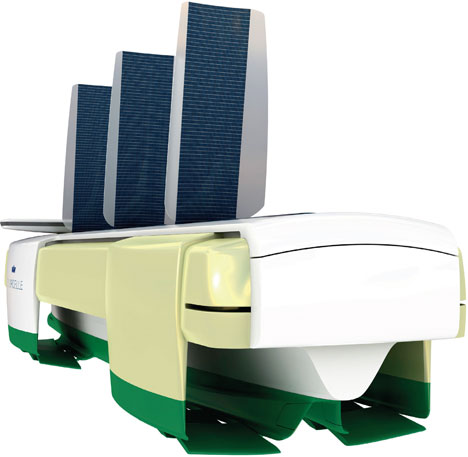
NEW SCIENTIST - WAVE POWERED SHIPS & CHEAP ELECTRICITY JULY 2011
SHIPS that harvest energy from the waves and store it in batteries could one day generate electricity from the world's oceans more cheaply than today's wave-power devices.
The ships would sail to a suitable location, drop anchor and start generating electricity from wave energy. Once their batteries were fully charged they would return to shore and feed the electricity into the grid.
Unlike conventional wave-power devices, the ships would not need undersea cables to link to the electricity grid, says Andre Sharon at Boston University and the Fraunhofer Center for Manufacturing Innovation, also in Boston. These cables typically cost more than $500,000 per kilometre and account for a significant fraction of the cost of conventional wave-generated electricity.
The 50-metre-long ships would harvest wave energy via buoys attached to their sides by pivoting arms. While the hull remains relatively stable, the buoys would bob up and down on the waves, causing the arms to pivot back and forth and drive a generator producing up to 1 megawatt of electrical power. The batteries are planned to have a capacity of 20 megawatt-hours, so the ships would have to stay at sea for at least 20 hours for a full charge. Sharon presented the concept at the Clean Technology 2011 Conference and Expo in Boston.
Unlike conventional wave-power devices, the power-generating mechanism will not have to withstand severe storms, as the ships could be kept in port during bad weather. Fixed wave-power generators must be built to cope with extremely high waves, which adds substantially to their cost, Sharon says. Costs could be cut further by retrofitting existing vessels, which could either have their own engines or be towed out to sea and back.
Sharon used 3D printing to produce a prototype, and tested it in a wave
tank. He calculates that the system should generate electricity at a cost of $0.15 per kilowatt-hour. This would make it cheaper than energy from existing wave systems, which costs between $0.30 and $0.65 per kWh.
Offshore wind energy costs from $0.15 to $0.24 per kWh, and
solar power around $0.30 per kWh.
Mark Jacobson, director of the atmosphere and energy programme at Stanford University in Palo Alto, California, calls the idea "very creative". He notes that unlike electricity from many other renewable sources, power from the batteries could be held back and used at times of peak demand. WAFT
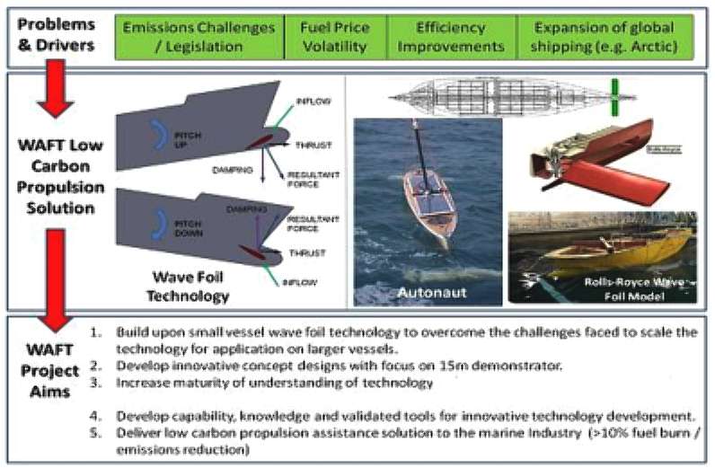
- ROLLS ROYCE Wave Augmented Foil Technology,
is a project part funded by the Technology
Strategy Board. The project was lead by Rolls-Royce, in collaboration with
MOST and SeaSpeed. The objective being to develop a small scale model for
hydrodynamic evaluation, taking that to a 15m demonstrator. The objective is to
scale the foils up for cargo vessels. Kystfangst, the 20m vessel mentioned
above, would have benefited from being longer. We look forward to reporting on
this project as more information become available. 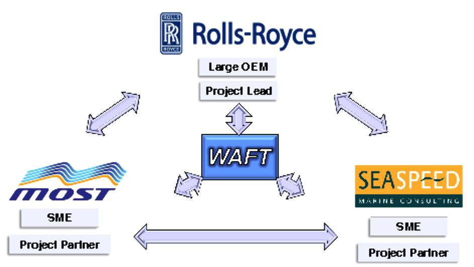

THE
ENGINEER JULY 2013 More nuclear, battery and gas-powered vessels are needed to cut shipping emissions in the absence of a single magic bullet solution, according to a new report. Diesel engines are likely to remain the most common form of shipping propulsion in the short term but converting ships to use liquid natural gas (LNG) would provide a cheaper, cleaner and well understood alternative, said the study from the Royal Academy of Engineering. In the medium-to-long term, the shipping industry needs to adapt current technologies and develop new ones that use fuel cells, batteries and nuclear reactors, augmented by renewable power sources such as wind and solar, the report concluded. Prof John Carlton of City University London, who led the working party that surveyed the propulsion options available shipping, said there was no single winning technology and different solutions would be needed for different vessels.
'We know that larger ships are more carbon-efficient than smaller ships and that slower ship speeds effectively reduce emissions,’ he said in a statement. ‘But fitting smaller engines in large ships may increase the risk of being under-powered in bad weather.’ Alongside LNG, which requires the development of a global infrastructure, gas turbines were described as a potential short-term solution that has been successfully used in niche areas of the marine market but faced the issues of expensive fuel and lower efficiencies than existing slower-speed diesel engines. In the medium term, biofuels, particularly those made from algae or other
mico-organisms, are seen as an alternative but further work is needed on their storage, handling, and impacts on health, safety and the environment.
Fuel cells are another option, with high-temperature solid oxide and molten carbonate models showing the most promise for propulsion, the report says, and low-temperature proton exchange membrane fuel cells for lower power generation. Nuclear ship propulsion produces no emissions and there is a significant body of experience of its use, but conventional methods of design, manufacture and operation would need a complete overhaul for commercial use, and issues of regulation and public perception would need to be addressed. It also requires high capital investment and a new global infrastructure support system. Battery technology is developing rapidly and produces no emissions, the report said. ‘However, full ship battery propulsion requires further technical development and is likely to be confined to relatively small ships.’ On the other hand, the report pointed to batteries’ potential in hybrid solutions for some
small - to medium-sized ships, providing recharging doesn’t increase overall emissions from land-based energy generation.
‘Hydrogen, compressed air and liquid nitrogen are likely to be long-term propulsion considerations,’ the report said. But all three require land-based sources of power for creation and distribution infrastructure. Royal Academy of Engineering president Sir John Parker said: ‘As for all industries, concerns about climate change require the reduction of greenhouse gas emissions from the shipping sector. ‘This entails higher fuel prices for low sulphur
fuels. It means that the industry must prepare for the new future and investigate alternative, more economic ship propulsion systems.’

THE
AUTONAUT
USV - 2013 The
AutoNaut has a fully scalable wave propulsion technology - this is beyond doubt
where foils have been used on fishing vessels such as the Kystfangst
above. A larger boat could
have more speed, except that the WAFT project found that 3 knots was about their
gain. But, research is needed to see what is possible and perhaps to provide a
common database for results that is easy to assimilate, comparing one technology
with another.
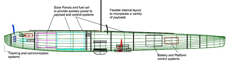
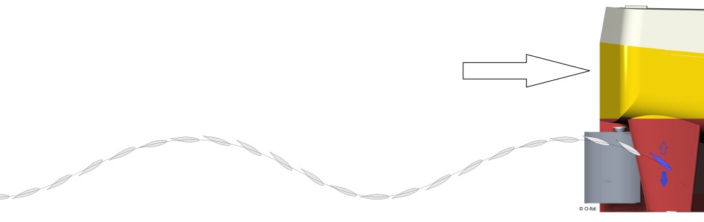
This
is the internal layout of the 3.5m Autonaut MOST
ASV - HISTORY 1st June 2013 MOST
won the £400k National Oceanography Centre (NOC) Phase 2 project under their ‘Long Endurance Marine Unmanned Surface Vehicles’ (LEMUSV) call.
The new hull design was ‘frozen’ 18th July and the build was well under way.
The team aim to bring all the sub-contracted parts together in November. This NOC Phase 2 project takes AutoNaut to final pre-production stage with all its systems in place and thoroughly tested. Sea trials
were scheduled for Portsmouth in December and Oban in February. The project will also enable
the company to get their original 3m AutoNaut to sea for longer periods in the autumn, working with Plymouth Marine Laboratory on their Western Channel Observatory, out by the Eddystone Lighthouse. 8th November 2013
Sister company MOST Ltd won a collaborative project with Rolls Royce Marine Ltd under the
Technology Strategy Board’s ‘Vessel Efficiency’ call to take the AutoNaut technology into manned ships. The contract was finalised and the first kick off meeting was held in November. As a technology leader in the marine field RR is an ideal partner for this development, owning both a stabiliser manufacturing company as well as ship testing and building facilities in
Norway. MOST (AV)’s original 3m AutoNaut will be chartered to MOST to become the initial research test bed. The output from this project will be a design for a 15m ship, then to be taken forward under an existing funding regime. New know-how from this research will feed back into the unmanned AutoNauts on which MOST (AV) concentrates.
1st December 2013
AutoNaut’s first sea trial with a real towed array proved a successful combination for two new UK designs. In a chilly 15 knot wind and small chop AutoNaut deployed and towed the 18 metre acoustic array. The vessel’s speed of around two knots was not noticeably changed and her steering remained good with a series of circles being completed without difficulty. This is part of
the NOC and
Dstl funded Phase 2 Long Endurance Marine Unmanned Surface Vessel (LEMUSV) project – see June news. The
team anticipated this success as a result of dummy towing trials with our earlier prototype, both at sea and in a
wave
tank, but it was great to see a real array in action with the new boat. The new miniaturised low profile array is provided by J+S Ltd, a UK engineering company based out of Barnstaple and Aberdeen. Ease of handling and the robust nature of the array was clearly demonstrated. The array was able to track a target of opportunity and with the absence of tow vessel noise, 360 degree coverage was achieved.
Andy Toms, Managing Director for J+S is quoted as saying: “This successful trial is the result of months of intensive sonar engineering work by our Product Development Team. The collaboration with
MOST (AV) demonstrates the potential of
the LPA technology as a lightweight, easily deployed, acoustic sensing system”
Mike Poole, Director of MOST (AV) is quoted as saying: “Our collaboration with J+S Ltd is a triumph of innovative UK engineering expertise at its best.”
Further trials will work up both the deployment procedure and data processing ready for AutoNaut’s scheduled demonstration trials in Portsmouth in December and off Oban in
Scotland in February.
The array can just about be seen as a pipe on the starboard side, and disappearing over the stern.”
AUTONAUT
SPECIFICATIONS
|
Platform
|
Monohull
|
|
Dimensions
|
3.5m
LOA, X 0.43m beam
|
|
Draft
|
0.3m
|
|
Displacement
|
120
Kgs
|
|
Average
speed
|
2
– 3 knots
|
|
Endurance
|
3+
months
|
|
NAVIGATION
|
|
Heading
sensor
|
Digital
compass module
|
|
GPS
|
GPS
receiver module
|
|
POWER
|
|
Propulsion
|
Direct
wave powered (pitch and roll). Aux propulsion (~1kt) for flat calm
conditions
|
|
Battery
|
720Wh
lead gel
|
|
Solar
PV
|
125Wp
|
|
Generator
|
45
watt methanol fuel cell, 20 litres fuel (22kWh of power)
|
MOST
CONTACTS MOST (Autonomous Vessels)
Ltd
Chichester Marina, Chichester
West Sussex, PO20 7EJ Tel:
+44 (0) 1243 511 421
+44 (0) 1822 840 612 Email:
info@autonautusv.com Youtube:
http://www.youtube.com/autonautusv

O
-FOIL BV - OSCILLATING WING PROPULSION The
O-Foil system is the reverse of wave energy capture from passive foils.
Instead, active foils are used to generate thrust, just like our fish-tail
example at the head of this page. We thought to include the system because
the technology is interrelated, but may not work so well in open sea
conditions, if for example, the foil oscillation conflicts with opposing
(potentially incoming) wave energy. Imagine though if it were possible to synchronize,
such as to amplify wave effect? MARIN
are reported to have performed extensive tests and calculations on the O-foil
concept with very positive results. The O-foil system is expected to be available
for market for inland vessels from 2013.
O-foil stands for “oscillating foil”, in other words: a flapping wing. This
patented technology, developed by O-foil b.v., is based on the natural swimming
motion of animals. The wing or foil simulates a tail fin action so
generating propulsion by creating lift in the water on each up and down
stroke. A conventional screw propeller does the same with a wing that
rotates. But unlike the screw propeller, the O-foil wing covers the entire width of the ship.
The propulsion surface is thus much larger which promises to increase
efficiency by up to 50% (claimed) and so cut fuel consumption
significantly. The O-foil thus reduces CO2 emissions from the burning
of diesel fuels.
ABOUT
O-FOIL
The O-foil propulsion system consists of a wide impellent wing, a hybrid drive train
(we presume diesel-electric) and an adapted steering system. O-foil is ideal for inland navigation or other vessels with limited draught. O-foil is a young company that focuses on offering new technologies to the shipping market.
O-foil develops innovations that offer new perspectives to inland navigation. O-foil creates opportunities for the inland navigation sector to improve profitability while satisfying increasingly strict regulations. The first ship
to be fitted with the O-foil wing propulsion, the MS Triade, is already in use. The conversion of this inland vessel was a complete success.
The company expect to present the measured results for fuel consumption and emissions
in 2014. We are keen to learn how reliable the reciprocating mechanism is
in long term use. 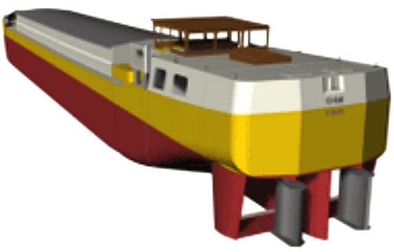
O-foil collaborates with the following companies:
Siemens, electric drive system
Teus Vlot Diesel & Marine, diesel &
electric installation and service
Van der Velden Marine Systems,
rudder system
SPONSORS


 CONTACTS
O-foil B.V. Benedendorpsweg 78
6862 WK Oosterbeek
The Netherlands
Tel: 0031 10 737 11 56
Email: info@ofoil.nl
DEVELOPMENT: A hybrid, wind, wave and solar powered vessel with computer controlled
energy harvesting
from nature and a modular SWASH hull design that provides development platforms for both civil and military
applications without having to redesign the whole vessel each time. The system
promises 7-10 knot speeds with zero emissions 24/7 and 365 days a year. This important research is
looking for collaborative partners for the EU Horizon
2020 call in 2014.

BLUEFISH
ZCC DEVELOPMENT PROJECT INDEX A-Z
LINKS
& REFERENCE
http://www.marin.nl/web/News/News-items/Ofoil-propulsion-concept-successfully-tested.htm
http://www.ofoil.nl./
http://folk.ntnu.no/eirikbo/wavepropulsion/index
http://www.theengineer.co.uk/engineers-called-on-to-develop-new-low-carbon-ship-propulsion
http://www.newscientist.com/wavepower-ships-could-bring-cheaper-clean-electricity
http://www.wavepropulsion.com/
http://www.boatdesign.net/windmill-wind-turbine-powered-boats-how-many-out-there-they-viable
http://www.forbes.com/2008/06/19/wave-powered-boat-tech-water08-cx_avb_0619waveboat.html
http://atlantic-power-cluster.eu/index.php/en/
http://blog.modernmechanix.com/wind-propeller-sails-proposed-for-liners/
http://en.wikipedia.org/wiki/Rotor_ship
http://www.sailwings.net/art.html
http://www.sailwings.net/rotaryhome.html
http://www.windthrusters.com/
http://www.sailwings.net/
Worlds-first-fuel-cell-ship-e2809eFCS-ALSTERWASSERe2809c-proves-ist-reliability-1780
http://www.ecomarinepower.com/wind-and-solar-ships
http://www.seaspeed.co.uk/Trials-and-Testing-Projects/south-boats
http://www.popsci.com/gear-gadgets/article/2008-02/wave-runner
http://www.rexresearch.com/waveboat/waveboat.htm
Ashburton
Guardian (1897). A boat with fins. Volume XVIII, Issue 4281, 30 August
1897.
Bose,
N. and Lien, J. (1990). Energy Absorption from Ocean Waves: In Proc. R. Soc.
Lond, vol.B 240, pp. 591–605.
Fabre,
O. (2008). Japan sailor takes on pacific in wave-powered boat. Reuters,
March 17, 2008. Retrieved June 29, 2011.
Gause,
J. A. (1966). Flexible fin propulsion for vessels GB Patent 1176559. Sept. 7, 1966. Patented Jan. 7,
1970
Gause,
J. A. (1967). Water-borne propulsion system flexible fin members US Patent 3,453,981.
Apr. 24, 1967 Jul 8 1969
Burnett, R. F. (1979). Wave energy for propelling craft - nothing new. The Naval Architect. Nov. 1979, p. 239.
Dybdahl, K. (1988). Foilpropellen kan revolusjonere skipsfarten. Teknisk Ukeblad/ Teknikk, no. 39, October 1988, pp. 10-11.
Anon.(1983). Wave power for ship propulsion. The Motor Ship, 64(757):67–69.
Berg, A. (1985). Trials with passive foil propulsion on M/S Kystfangst. Project no. 672.138. Technical report, Fiskeriteknologisk Forskningsinstitutt, Fartøyseksjon, Marinteknisk senter, Håkon Håkonsensgt. 34, 7000, Trondheim.
|